
How to Set Up a Cluster of x86 Servers with Oracle VM 3
by Kris Bakke and Jeffrey Kiely
Published May 2012
Step-by-step instructions for using Oracle VM 3 to set up a cluster of highly available Sun x86 servers.
Introduction
This article describes the process of setting up a cluster configuration of Oracle VM 3 using Oracle's Sun x86 systems. The primary design goal for this cluster configuration is high availability (HA). Thus if one server or network port goes down, other components should automatically pick up its load. Server redundancy is inherent in the virtualized architecture, and the design also utilizes multiple networks with bonded ports (see the "Bond the Management Network Ports" section). This enables redundant network connections between the virtualized servers in the Oracle VM server pool and the management server, thus giving Oracle VM Manager continuous access to the servers in the event of a single network failure.
The hardware and software infrastructure described in this article is considered a cloud infrastructure because it offers the following capabilities:
- On-demand access—A shared pool of configurable computing resources is available as needed for running application services.
- Elastic scalability—Add more servers, memory, disk, and so on and your applications automatically take advantage of it without having to know about it.
- Rapid provisioning—The management environment enables rapid provisioning and replication of system resources and virtual machine (VM) guest environments.
- High availability—The infrastructure is configured to support continued operation in the event of a component failure, such as a server or network port.
- Portability—VMs are not tied to a hardware platform; they can be live-migrated and still access their storage.
Our test configuration used blade servers running within Oracle's Sun Blade 6000 modular system to host the Oracle VM server pool. The setup process for Oracle VM and the network would be essentially the same if you were to use rackmount servers rather than blade servers. The procedure described in this article also works for any OS supported by Oracle VM.
We start our setup process from the point where Oracle VM has already been installed on all of the Sun x86 systems in the configuration. The first step is, therefore, to let Oracle VM Manager discover the bare-metal systems available to participate in the Oracle VM server pool. We then proceed to configure the network resources to create a cluster of Oracle VM virtual machines running in the blade server environment. The last step of the process defined in this article is to create the Oracle VM server pool and assign a storage repository.
This article covers the assignment of a storage repository for the Oracle VM server pool, but it does not discuss the details of configuring the storage environment or the storage networking. Also not covered in this article is the process of setting up the application environment that will run on the virtual machines. The virtual machine software stack, often called a golden image, is typically established on one VM and then replicated to other VMs for rapid deployment and easy maintenance. If all nodes on your cluster will run the same application environment, you can also install the application environment as part of the golden image that you will replicate throughout the VMs. If your VMs will run different applications, the golden image might consist of just a preconfigured version of the operating system of your choice.
Additional information about how to set up the storage environment, software infrastructure, and other aspects of an enterprise cloud deployment can be found in the "Oracle Optimized Solution for Enterprise Cloud Infrastructure—Implementation Guide (x86-Linux)" white paper.
About Oracle's Sun x86 Systems
Oracle's Sun x86 systems are available in both rackmount and blade form factors and include an integrated Oracle software stack. Every model comes complete with virtualization, choice of OS, infrastructure provisioning, and Oracle's unique application-to-disk system management environment—all at no extra charge on servers with a support contract. In addition to simplifying cloud management, Sun x86 systems also provide large memory capacities and scalable performance based on the Intel Xeon processor E5-2600 CPU. These features make Sun x86 systems an extremely good fit for an enterprise cloud infrastructure.
Configuration and Network Topology
This article is based on the same server and storage configuration used in the Oracle Optimized Solution for Enterprise Cloud Infrastructure. This test configuration was deployed as part of the effort to identify best practices for the hardware and software architecture and implementation in the Oracle Optimized Solution for Enterprise Cloud Infrastructure. Our test configuration consists of the following major components:
- One Sun Blade 6000 modular system with three Sun x86 server blades for running Oracle VM guests
- One Sun x86 rackmount server running Oracle VM Manager
- Two of Oracle's Sun ZFS Storage Appliance controllers in a cluster configuration
- Two top-of-rack network switches connected by an HA interconnect
Figure 1 shows the network topology for connecting these components. Oracle VM Manager is deployed on a single Sun x86 rackmount server while the Oracle VM guest virtual machines run on the three blade servers in the Sun Blade 6000 modular system.
The top-of-rack switches simplify the network cabling and enable redundant connections between all servers and storage systems in the configuration. The blade server modules in the Sun Blade 6000 modular system are surfaced to the network through two Sun Blade 6000 Ethernet Network Express Modules (NEMs). These are referred to as NEM0 and NEM1 in the figure.
Quad SFP+ (QSFP+) network links are used for fiber-based physical network connections to the Sun Blade 6000 server modules. There are three QSFP+ ports from each of NEM0 and NEM1, resulting in a total bandwidth of 120 Gb/sec for each NEM. This network configuration is designed to deliver both high performance and redundancy for high availability. The bandwidth available in this network configuration is also intended support up to 10 server modules in the Sun Blade 6000 chassis. Since our test configuration had only three blade servers in the Sun Blade 6000 chassis, network throughput was not really challenged in our tests.

Figure 1. Network Topology for Connecting the Components
Discover Oracle VM Server for x86 Host Systems as a Resource
The first step in setting up Oracle VM is to discover existing host systems that are on the same network as the server running Oracle VM Manager. Oracle VM Manager has a Discover Servers feature that makes it easy to bring the available servers into a default "unassigned" server pool where you can then manage them from within Oracle VM Manager. The servers must have already been assigned an IP address on the same network as Oracle VM Manager. Otherwise, they will not be visible to the Discover Servers process of Oracle VM Manager.
After logging in to Oracle VM Manager, you should see a "home" view similar to Figure 2.
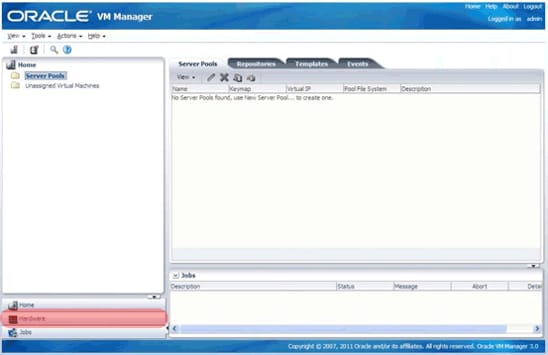
Figure 2. Home View of Oracle VM Manager
Click the Hardware icon on the lower left (highlighted in red in Figure 2). This will take you to the Hardware view shown in Figure 3, where you can add networking and external storage as resources. Use Discover Servers to add them as resources by right-clicking the Resources folder in the navigation tree and selecting Discover Servers from the menu.

Figure 3. Hardware View
Add the host systems, as shown in the Figure 4. You may use a range of IP addresses, as shown, or add them one at a time.
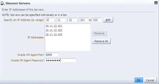
Figure 4. Adding IP Addresses
By default, the discovery process will add all the newly discovered servers to the Unassigned Servers resources pool. As shown in Figure 5, the Unassigned Servers pool now contains three servers: MyServer1, MyServer2, and MyServer3. These represent the three blade servers in the Sun Blade 6000 modular system. The newly discovered x86 host systems will remain in the unassigned pool until you assign them to a server pool. A new server pool will be created during a later step in this article and the servers will be assigned at that time.
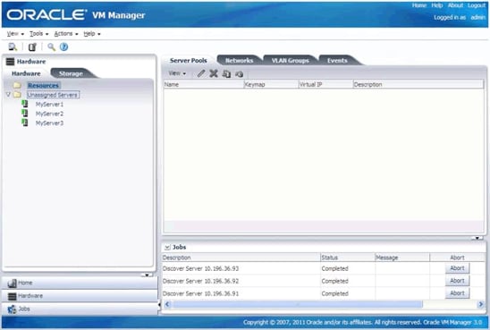
Figure 5. Unassigned Servers Pool
Set Up Network Resources for Oracle VM
Oracle VM 3 allows finer control over networking compared to previous versions of Oracle VM. Oracle VM Manager can now be used to assigning network roles and subnets to network devices on the x86 host systems, alleviating the need to log in to the host systems to configure networking by hand.
Most data centers will have multiple subnets with specific roles, such as a production front end where all users can connect to servers, databases and applications (public network), dedicated storage (storage network), dedicated out-of-band server management (management network), and so on.
To keep things relatively simple, yet show some of the new powerful features of Oracle VM 3, this article describes the process of setting up two subnets as follows:
- A management subnet used for out-of-band management of the Oracle VM environment
- A public subnet used for general access to storage and Oracle VM guests (as well as databases and applications)
A single network was set up during the installation process for Oracle VM Manager and Oracle VM Server for x86. This existing network will be used as the management network and is the same network on which bare-metal x86 servers were discovered in process described above. The second step will be to create a new network that will become the public network for access to storage and Oracle VM guests.
To avoid confusion with network names, we will change the name of the existing management network to "Management network." This is not a required change and is only meant to help reduce confusion about network roles in subsequent steps. Please adjust the names and roles of the subnets in the following steps to conform to your particular network environment. If only a single subnet exists within the network, just modify the existing network and assign all "uses" to that one subnet. Then skip the later "Create an Additional Public Network" section.
Configure the Management Network
Ensure that Resources is selected in the navigation pane, and then select Networks from management tab, as shown in Figure 6. Then click the Edit icon from the management toolbar just below the Networks tab.
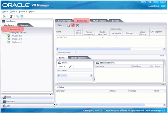
Figure 6. Edit Icon
A dialog box from the Edit Network wizard will allow you to change the network name from the default subnet address to any string. In this case, change the Name field to Management network, as shown Figure 7, to allow easy identification in later steps.
The Network Use section on the right side of the GUI refers to the type of traffic for the subnet. In our test configuration, we had only one subnet. However, since most environments will have sufficient network ports to support two separate networks, we've written this article to show the steps required to create two networks. Thus, we will detail the steps required to create a management network here in this section and a subsequent section describes how to create an additional network for public use (VM guests and storage roles).
In our management network, we did not select the Storage or Virtual Machine checkboxes as Network Use roles, because this type of traffic will be configured in the public network in a subsequent section. As mentioned earlier, if you had only one subnet, then you would need to select the Storage and Virtual Machine options here in the management network and then skip the later "Create an Additional Public Network" section.
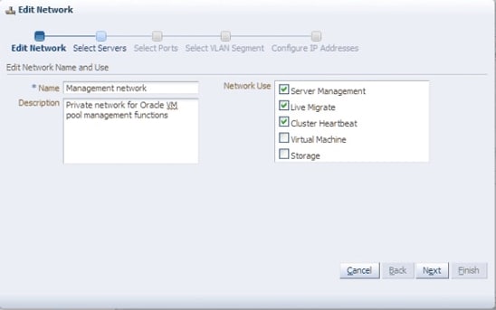
Figure 7. Changing the Network Name and Selecting Network Use Roles
The wizard will then step through the remaining four tasks. Simply accept the default on all subsequent dialog boxes until the Finish button becomes active. The result should look like Figure 8.

Figure 8. Configured Management Network
Bond the Management Network Ports
The management network is critical to the operation of the server infrastructure, so it should be configured for high availability. This means that the management network ports should be bonded to allow the secondary network link to take over if the primary network links fails.
The bonding process described below establishes a logical connection between a primary and a secondary network port. The primary port remains the sole active port unless a problem occurs, and the secondary port is inactive unless the primary port fails. These bonded ports will allow the blade server host systems to have uninterrupted management access even if the physical network layer for one of the network ports fails.
The steps that are described below assume that the basic network configuration is already in place. In other words, if network aggregation is to be used to consolidate multiple physical ports into a single logical network connection, that configuration has already been established.
We'll now set up network port bonding by repeating the steps below for each of the three servers.
First, select a server from the Unassigned Servers pool and click the Bonding tab.
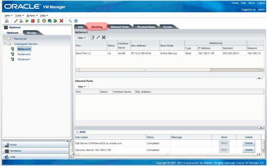
Figure 9. Bonding Tab
There is an already existing bond (bond0) that was assigned to Bond Port(1) during the initial installation of Oracle VM Manager. Select this bond port and then select the Edit icon, as shown in Figure 10.
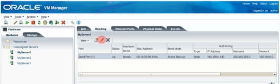
Figure 10. Editing Bond Port(1)
This brings up the Edit Port dialog box, as shown in Figure 11. From here, you can add the other management network port to the bond group. Note that the bonding type shown in the lower left corner of the screen is Active Backup. This means that the active port will handle the entire network load unless it fails. If that happens, the secondary port will then take over the entire network load.
Move the secondary network port from the Available Ports list to the Selected Ports list, and click OK to continue.
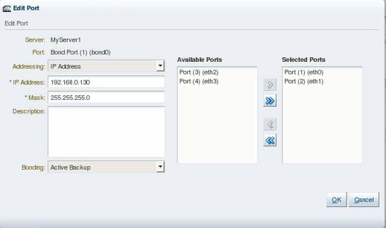
Figure 11. Edit Port Dialog Box
As shown in Figure 12, multiple ports will now be associated with the bond.
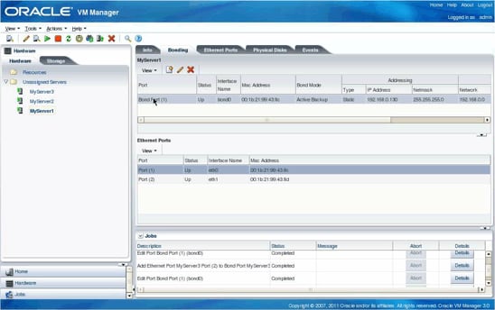
Figure 12. Multiple Ports Are Now Associated with Bond Port(1)
Repeat the steps above to establish a bond/port group for each of the host systems in the environment.
Create an Additional Public Network
The process above focused on establishing high availability for the management network. Now we're ready to set up a new public network that will be used for virtual machine I/O and storage I/O. This new network will allow Oracle VM Server for x86 host systems and Oracle VM Manager to access storage—as well as databases, applications, and so on—running on Oracle VM guests.
The create network task basically configures another network interface/bridge on the host servers. The network information is provided by the Oracle VM administrator, as shown in the Oracle VM Manager Create Network wizard screenshots that follow.
Start by clicking the Create Network icon from the management toolbar just under the Network tab, as shown in the Figure 13.
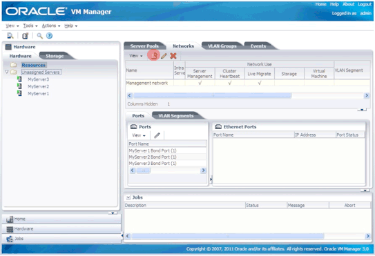
Figure 13. Initiate the Create Network Function
Figure 14 shows the supported network types. Select the Create a network with bonds/ports only option because we want high availability. VLANs do not offer high availability, but they can be used with bond ports in a hybrid network. VLANs and hybrid networks are beyond the scope of this article. For more information about configuring VLANs, please refer to the Sun Ethernet Fabric Operating System VLAN Administration Guide.
Click Next.
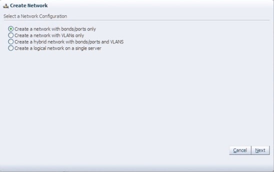
Figure 14. Creating a New Network
Enter a name for the new network in the Name field and select the Virtual Machine and Storage checkboxes, as shown in Figure 15.
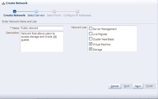
Figure 15. Naming the New Network
Next, select the host systems where the new network will be created and configured. All three of our blade servers will be part of this public network, so all of them are in the Selected Servers list in Figure 16.
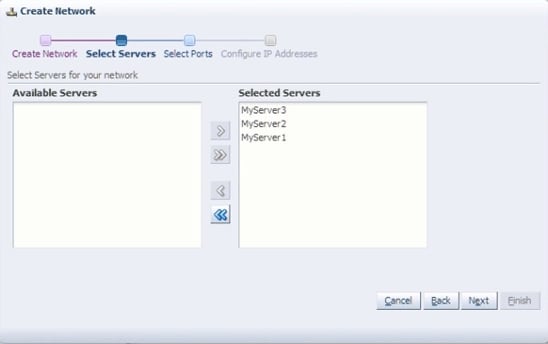
Figure 16. Select the Host Systems to be Configured into the Network
The next step is to identify the port/interfaces. In Figure 17, the port/interfaces do not show the Linux name for the interface, such as eth1. Instead, they are shown as the logical names: such as Port(2),. Choose the appropriate interface to configure on each Oracle VM 3 server host, according to what is relevant to the environment. In our case, we're using Port(2) as the public network. Port(1) was already defined as the management network. Port(3) and Port(4) are unused.

Figure 17. Selected Ports
Finally, provide the IP address information of the storage subnet and Oracle VM guests on each host system.
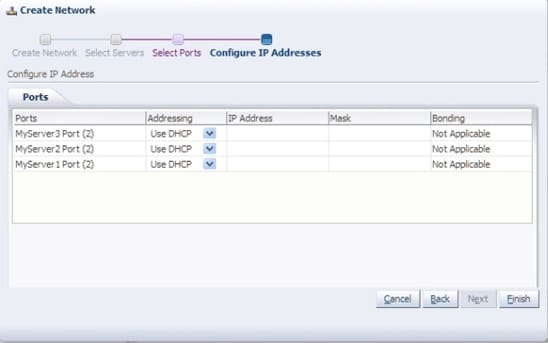
Figure 18. Configuring IP Addresses
Figure 19 shows the public network after it has been configured on each host system.
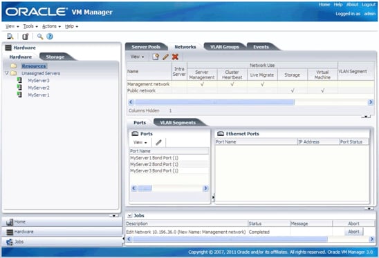
Figure 19. Configured Public Network
Create the Virtual MAC Addresses
The last network task is to create a pool of virtual Ethernet (MAC) addresses for the Oracle VM guests. The virtual Ethernet addresses will be randomly assigned from the pool as each Oracle VM guest is created.
Note: The Oracle VM administrator can assign specific MAC addresses to specific Oracle VM guests by changing the randomly assigned MAC addresses, as will be seen in a later step.
To begin, choose Vnic Manager from the Tools menu at the top of the GUI, as shown in Figure 20.
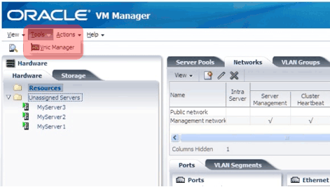
Figure 20. Opening the Vnic Manager
Enter any valid hex numbers for the last three octets in the Virtual Network Interface Card Manager dialog box (the first three octets cannot be changed), and then click Generate.
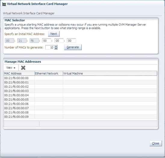
Figure 21. Specifying MAC Addresses
Click Close once the pool of MAC addresses has been generated. The pool of MAC addresses will now be available for automatic assignment to any Oracle VM guests that are created. More Ethernet addresses can be generated later if needed.
Create the Oracle VM 3 Server Pool
Now we want to create a server pool that will contain the server resources that can be used by Oracle VM Manager when allocating resources for Oracle VM guests. The server pool requires a list of physical servers as well as networking and storage resources.
A server pool can be created only after all the other resources, such as host systems, networking, and storage, have been added to Oracle VM Manager. The host systems and networking components were configured above and are, thus, already known by Oracle VM Manager. The storage systems are assumed to have been registered with Oracle VM Manager at an earlier stage.
Select the Home shortcut in the navigation views pane to change the view to Home.

Figure 22. Returning to the Home View
Right-click the Server Pool directory and select Create Server Pool.
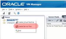
Figure 23. Opening the Create Server Pool Dialog Box
In the Create Server Pool dialog box, enter the server pool name, the relocatable virtual IP address, and the NFS export used for the server pool file system. The name MyServerPool has been entered as the server pool name in Figure 24. The virtual IP address is an address that will always be associated with the host system currently designated as the server pool master. Servers are not added to the server pool until later.
Select the Activate Cluster checkbox, as shown in Figure 24, to indicate that this server pool will be part of a cluster. Also select Network File System rather than Physical Disk, because we'll be using shared storage on the Sun ZFS Storage Appliances.
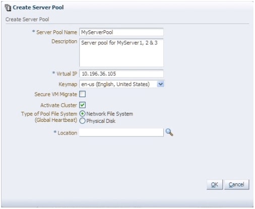
Figure 24. Create Server Pool Dialog Box
Click the Location icon, shown in Figure 25, to select the server pool file system. This allows you to identify the NFS mount for use by the cluster of virtual machines.

Figure 25. Location Icon
This will bring up a dialog box that shows shared storage resources that have been previously registered with Oracle VM Manager. Select the NFS mount to be used for the server pool file system.
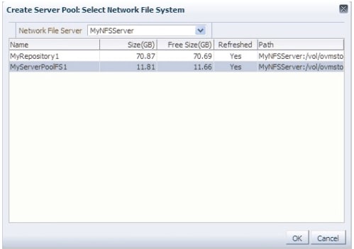
Figure 26. Selecting an NFS Mount
Click OK to create the server pool. The server pool does not yet have server host systems or a storage repository associated with it.

Figure 27. Creating the Server Pool
The next step is to add host systems to the newly created server pool. Simply right-click the server pool name and select Add/Remove Servers.
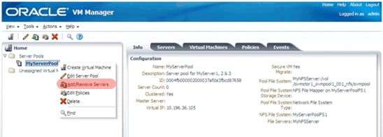
Figure 28. Opening the Add/Remove Server from Server Pool Dialog Box
Select the host systems that will be included in the server pool, as shown in Figure 29.
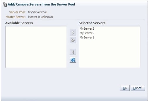
Figure 29. Selected Servers
The server host systems will be moved from the unassigned folder and will now appear under the server pool name in the navigation tree, as shown in Figure 30.
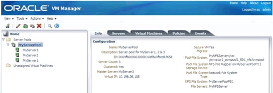
Figure 30. Selected Servers Added to the Server Pool
The server pool is almost completed and just needs a storage repository.
Assign a Storage Repository
The final step in the process of creating a server pool is to assign an NFS mount that will act as the centralized storage repository where all of the Oracle VM guest files, templates, and other resources will reside for the entire server pool.
Select the Repositories tab and then click the Create Repository icon on the management pane toolbar just under the tab.
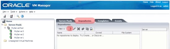
Figure 31. Create Repositories Icon
Enter a name for the storage repository, choose Network File Server for the Repository Location, and then click the magnifying glass icon to bring up the Select Network File System dialog box.
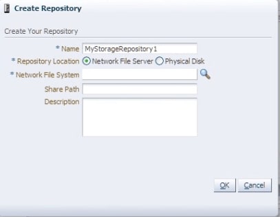
Figure 32. Create Repository Dialog Box
Use the Select Network File System dialog box to choose the NFS export that was created earlier for use as a storage repository. Click OK when completed.
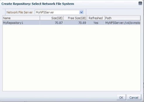
Figure 33. Choosing the NFS Export
Add an optional description and click OK to complete the creation of a storage repository.
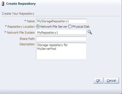
Figure 34. Creating the Storage Repository
At this point, the storage repository has been created, but is not yet assigned to any server pool. So, the final step for creating a server pool is to assign the newly created storage repository to the specific host systems that will need access to the centralized storage.
To make this assignment, select the newly created storage repository, and then click the Present-Unpresent Selected Repository icon (up/down green arrow) from the toolbar just below the Repositories tab.
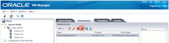
Figure 35. Present-Unpresent Selected Repository Icon
Select all of the server host systems that will have access to the repository and then click OK.
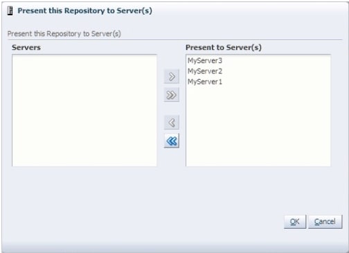
Figure 36. Selecting Servers for the Repository
The storage repository will now show the host systems whenever the storage repository is selected in the Repositories tab. Note that host systems can have access to multiple storage repositories, so you can repeat the above steps for other storage repositories if additional storage repositories are desired.

Figure 37. Configured Cluster
The Oracle VM cluster is now ready for Oracle VM guest images to be created.
Conclusion
By performing the steps described in this article, you will have completed the core tasks to set up a highly available enterprise cloud infrastructure. The remaining steps include configuring the storage environment and installing other software components, such as the Oracle Database. These steps and more are described in the "Oracle Optimized Solution for Enterprise Cloud Infrastructure—Implementation Guide (x86-Linux)" white paper.
See Also
Additional information about the latest Sun x86 systems is available on the Sun x86 Systems Website.
About the Authors
Kris Bakke has spent a combined 16 years at Oracle and Sun Microsystems before Sun was acquired by Oracle. His current responsibilities include developing the Oracle Optimized Solution for Enterprise Cloud Infrastructure, which provides an integrated hardware and software infrastructure that is cloud-ready. He has previous experience in product marketing and management as well as solution development for database backup, virtualization, data protection, cloud computing, and video surveillance.
Jeff Kiely is a Senior Technical Product Manager in Oracle's Sun x86 systems group and has been involved with the past two generations of x86 servers. He has held prior roles as a hardware engineer and a support engineer for x86 systems for over 7 years at Fujitsu America.