Technical Article
Deploying the Oracle Solaris Integrated Load Balancer in 60 Minutes
Amir Javanshir
Published February 2014
Hands-On Labs of the System Admin and Developer Community of OTN
This lab demonstrates how the Integrated Load Balancer feature of Oracle Solaris provides an easy and fast way to deploy a load-balancing system. It also shows how to use the different types of load-balancing modes offered by the Integrated Load Balancer.
Table of Contents
Introduction and Lab Objective
This document details all the actions that were done during the Oracle OpenWorld Hands-On Lab 10181 session.
Note: You can also run this lab from your home or office on an x86 server, desktop, or laptop.
Oracle Solaris 11 provides an out-of-the-box layer 3 and layer 4 load-balancing feature known as the Integrated Load Balancer. This feature intercepts incoming requests and handles the redirection toward back-end servers based on customized load-balancing rules. The Integrated Load Balancer can turn any Oracle Solaris 11 server into a cost-effective yet powerful load-balancing system.
This hands-on lab was created for application architects or system administrators who need to deploy and manage a load-balancing system. It provides an overview of the entire process of enabling, configuring, and using the Integrated Load Balancer. As a concrete example, a simple Apache Tomcat web application is deployed on multiple Oracle Solaris Zones (another feature of Oracle Solaris), and the Integrated Load Balancer is used to showcase different load-balancing scenarios.
During this lab, you configure and use the Integrated Load Balancer inside an Oracle Solaris Zone to balance the load towards three Apache Tomcat web servers running a simple JavaServer Pages (JSP) application specially developed for this lab.
Prerequisites
The following actions need to be performed to prepare the lab environment before the actual lab can be started:
- Installing Oracle Solaris 11.1
- Creating virtual switches (etherstubs) and virtual NICs (VNICs)
- Configuring the global zone's VNIC (
gz_1) - Configuring four Oracle Solaris Zones: one to host the Integrated Load Balancer (
ilb-zone) and three to host the web servers (web1,web2, andweb3) - Configuring
ilb-zone, including installing the packages needed for the lab (for example, Apache Tomcat 6) - Configuring the
/etc/hostsfile - Enabling SSH connections as
root - Creating a JSP test file that can be used to test the Integrated Load Balancer
- Cloning
ilb-zoneto quickly installweb1,web2, andweb3 - Configuring the second VNIC of
ilb-zone(public interface 10.5.1.1) - Installing Apache JMeter and creating a test file that can be used as an alternative way to test the Integrated Load Balancer
To run this lab from your home or office, do the following:
- Ensure the x86 machine you will use has the following:
- At least 8 GB of RAM and two cores CPU
- An x86 operating system supported by Oracle VM VirtualBox, for example, Oracle Solaris for x86, Microsoft Windows, most Linux distributions, or Apple Mac OSX
- Perform the steps in "System Preparation (Prerequisites for the Lab)" section to prepare the lab environment by performing the actions described above.
Summary of the Lab Exercises
After you prepare the environment on your x86 machine by performing the steps in the "System Preparation (Prerequisites for the Lab)" section, you will execute the following lab exercises:
- Start the Oracle Solaris 11 virtual machine in Oracle VM VirtualBox.
- Log in to the Oracle Solaris 11 server.
- Check the current environment.
- Enable the Integrated Load Balancer.
- Verify the web environments.
- Configure and test the load balancer in Network Address Translation (NAT) mode.
- Create and test a customized health check script.
- Configure and test the load balancer in Direct Server Return (DSR) mode.
- Add a server to and remove a server from the back-end server group.
Technologies Used in This Lab
In order to emulate on a simple x86 machine the network and server topography that is needed to test a load balancer, this lab relies on the following technologies, which are built into Oracle Solaris 11:
- Oracle Solaris Zones for server virtualization
Oracle Solaris Zones technology offers the ability to create different isolated environments to suit the needs of particular applications, all on the same instance of Oracle Solaris. Each environment acts as a "real" server with its own host name, IP address, and IP stack. Table 1 shows some common commands used during this lab.
Table 1. Common Oracle Solaris Zones commands.
Purpose Command List all zones and their status zoneadm list -civLog in to a zone zlogin zone_nameor
ssh root@zone_host_nameBoot a zone zoneadm -z zone_name bootReboot a zone zoneadm -z zone_name rebootShut down a zone zoneadm -z zone_name shutdownThe following zones are created for this lab:
[root@kafka]# zoneadm list -civ
ID NAME             STATUS     PATH                           BRAND    IP
0 global           running    /                              solaris  shared
1 ilb-zone         running    /zones/ilb-zone                solaris  excl
2 web2             running    /zones/web2                    solaris  excl
4 web1             running    /zones/web1                    solaris  excl
- web3             installed  /zones/web3                    solaris  excl
A zone's status can be
running,installed(shut down), orconfigured(not installed).The host name of the global zone for this lab is
kafka. - Network virtualization
Oracle Solaris 11 provides, among other network features, virtual network interface cards (VNICs) and virtual switching (etherstubs), which enable the creation of a virtual data center in a box. Table 2 shows some common commands used during this lab.
Table 2. Common network virtualization commands.
Purpose Command List all physical NICs dladm show-physList all VNICs dladm show-vnicList all etherstubs dladm show-etherstubList all IP interfaces ipadm show-ifList all IP addresses ipadm show-addrShow the routing table netstat -rn - Oracle Solaris Service Management Facility
The Service Management Facility feature of Oracle Solaris replaces the legacy
initscripting mechanism for managing system and application services, and it is used in this lab to manage the Integrated Load Balancer and Tomcat services. Table 3 shows some common commands used during this lab.Table 3. Common Service Management Facility commands.
Purpose Command List all services svcs -aList the status of a service svcs service_name
or
svcs -l service_name(for more details)Enable a service svcadm enable service_nameDisable a service svcadm disable service_nameRestart a service svcadm restart service_nameRetry setting online a service that is in maintenance svcadm clear service_nameA service can be
online(enabled),disabled, or inmaintenance(it can't go online).
Global Lab Architecture
Figure 1 provides a global, detailed view of the architecture of the lab. The global zone hosts two networks and four zones.

Figure 1. Lab architecture.
Note: This is the global architecture used during the lab; however, the web1, web2, and web3 zones are connected only to the private (red) network at the beginning of the lab in order to use the load balancer in NAT mode. Later on, one of the exercises will consist of connecting them to the public (blue) network in order to operate the load balancer in DSR mode.
System Preparation (Prerequisites for the Lab)
This section explains how to prepare your x86 machine before starting the lab exercises. All commands are executed as root.
Install Oracle Solaris 11.1
The very first step is to install Oracle Solaris 11.1 in Oracle VM VirtualBox. (If you do not already have Oracle VM VirtualBox on your x86 machine, download and install it.)
You can download Oracle Solaris 11.1 here: http://www.oracle.com/solaris/solaris11/downloads/solaris-downloads.html.
Several installation media are available: Choose "Oracle Solaris 11.1 Live Media for x86" since this will install Oracle Solaris 11.1 with a full graphical environment. Although having a graphical environment is not a prerequisite for using the Integrated Load Balancer, it is recommended for this lab.
Create Virtual Switches and VNICs
Once you have installed Oracle Solaris 11, log in and then run the following commands to create the virtual switches (etherstubs) and VNICs.
[root@kafka]# dladm create-etherstub switch1
[root@kafka]# dladm create-etherstub switch2

[root@kafka]# dladm create-vnic -l switch1 gz_1
[root@kafka]# dladm create-vnic -l switch1 ilb_1
[root@kafka]# dladm create-vnic -l switch1 web1_1
[root@kafka]# dladm create-vnic -l switch1 web2_1
[root@kafka]# dladm create-vnic -l switch1 web3_1
[root@kafka]# dladm create-vnic -l switch2 ilb_2
[root@kafka]# dladm create-vnic -l switch2 web1_2
[root@kafka]# dladm create-vnic -l switch2 web2_2
[root@kafka]# dladm create-vnic -l switch2 web3_2
Configure the Global Zone's VNIC
An internal "public" network will be created; therefore, the global zone needs to be connected to a virtual switch (switch1) via a VNIC (gz_1). To accomplish this, run the following commands:
[root@kafka]# ipadm create-ip gz_1
[root@kafka]# ipadm create-addr -T static -a 10.5.1.6/24 gz_1/v4
Configure Four Oracle Solaris Zones
- Create a zone configuration file called
/root/ilb-zone.cfgusing the content shown in Listing 1:create -b set brand=solaris set autoboot=true set zonepath=/zones/ilb-zone set autoboot=true set ip-type=exclusive add net set configure-allowed-address=true set physical=ilb_1 end add net set configure-allowed-address=true set physical=ilb_2 endListing 1. Content for
/root/ilb-zone.cfgfile. - Create a
web1zone configuration file called/root/web1.cfg using the content shown in Listing 2:create -b set brand=solaris set autoboot=true set zonepath=/zones/web1 set autoboot=true set ip-type=exclusive add net set configure-allowed-address=true set physical=web1_1 end add net set configure-allowed-address=true set physical=web1_2 endListing 2. Content for
/root/web1.cfgfile. - Create the two remaining zone configuration files (
web2.cfgandweb3.cfg) by usingweb1.cfgas a template and replacing "web1" with "web2" or "web3," respectively. - Configure the zones using the configuration files you just created:
[root@kafka]# zonecfg -z  ilb-zone -f /root/ilb-zone.cfg
[root@kafka]# zonecfg -z  web1 -f /root/web1.cfg
[root@kafka]# zonecfg -z  web2 -f /root/web2.cfg
[root@kafka]# zonecfg -z  web3 -f /root/web3.cfg
Install and Configure ilb-zone
- Install the
ilb-zonezone:[root@kafka]# zoneadm -z ilb-zone install - Once the installation is done, boot the zone and log in to the console so you can perform the first-boot system configuration, as you would for any Oracle Solaris installation:
[root@kafka]# zoneadm -z ilb-zone boot [root@kafka]# zlogin -C ilb-zone - In the System Configuration Tool (see Figure 2), press F2 so you can specify the required system configuration information, such as time zone, root password, and so on. The most important information concerns the network configuration.

Figure 2. System configuration: Welcome screen.
In the Network screen, set the computer name to
ilb-zoneand choose to configure the network manually (see Figure 3).
Figure 3. System configuration: Network screen.
In the Manually Configure screen (see Figure 4), choose the private interface
ilb_2and configure it with the following information:- IP address: 192.168.1.10
- Netmask: 255.255.255.0
- Router (Gateway): 192.168.1.10
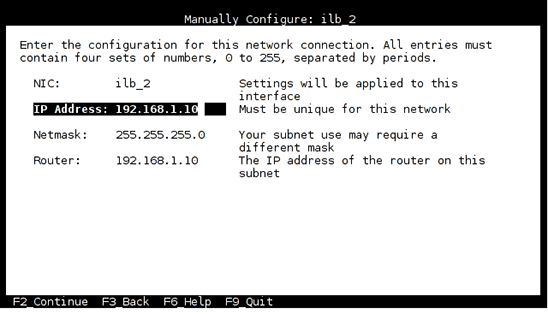
Figure 4. System configuration: Manually Configure screen.
No name services need to be configured (DNS or NIS).
Finally, choose the time zone and the root password to finalize the system configuration.
Note: Only one network interface card (NIC) can be configured using the system configuration tool; therefore, the public interface
ilb_1will be configured later by logging in to the zone. - Once you have completed the system configuration for
ilb-zone, log in and add the extra packages needed for this lab (for example, Apache Tomcat):[root@kafka]# zlogin ilb-zone [root@ilb-zone]# pkg install solaris-large-server tomcat tomcat-examples
Configure the /etc/hosts File
Add the content code shown in Listing 3 to the /etc/hosts file in the global zone and in the ilb-zone zone.
::1             localhost
127.0.0.1       localhost loghost
10.5.1.6 kafka
10.5.1.10 ilb-zone
10.5.1.11 web1
10.5.1.12 web2
10.5.1.13 web3

10.5.1.50 vip

192.168.1.10 ilb-zone-priv
192.168.1.11 web1-priv
192.168.1.12 web2-priv
192.168.1.13 web3-priv
Listing 3. Content for the /etc/hosts file.
Allow SSH Connections as root
Edit the file /etc/ssh/sshd_config and change the line PermitRootLogin no to PermitRootLogin yes.
Create the JSP Test File
To test the load balancer, this lab uses a simple JSP file that will dynamically print the IP address of the back-end server that served our request.
Add the JSP code shown in Listing 4 to a file called ilbtest.jsp under the /var/tomcat6/webapps/ROOT directory in the ilb-zone zone.
Note: You might wonder why we install Tomcat and create a JSP file in ilb-zone zone, given that during the lab, this zone will act as a load balancer and not as a web server. The reason is that we will be using this first-created zone as a template for all the other zones. Therefore, creating the zones that will act as web servers will simply be a matter of cloning this zone. One advantage of using this method is that less disk space is consumed, but this method is also a huge time saver, because cloning an existing zone to create a new one takes only a matter of seconds.
<html>
<head>
<title>Solaris 11 ILB Lab</title>
</head>
<body>
<%@page import="java.net.InetAddress;" %>

<TABLE width=100% border="0" cellpadding="3">
<TR>
    <TH align="center"><h2>Client</h2></TH>
    <TH align="center"><h2>Load Balancer</h2></TH>
    <TH align="center"><h2>Server</h2></TH>
</TR>
<TR>
    <TD align="center">
    <TABLE cellpadding="2">
    <TR>
        <TD>Client Host name:</TD>
        <TD><b><%= request.getRemoteHost() %></b></TD>
    </TR>
    <TR>
        <TD>Client IP:</TD>
        <TD><b><%= request.getRemoteAddr() %></b></TD>
    </TR>
    <TR>
        <TD>Client Port:</TD>
        <TD><b><%= request.getRemotePort() %></b></TD>
    </TR>

    </TABLE>
    </TD>
    <TD align="center">
    <TABLE cellpadding="2">
    <TR>
        <TD>Virtual Host name:</TD>
        <TD><b>vip</b></TD>
    </TR>
    <TR>
        <TD>Virtual IP:</TD>
        <TD><b>10.5.1.50</b></TD>
    </TR>
    <TR>
        <TD>VIP Port:</TD>
        <TD><b><%= request.getServerPort() %></b></TD>
    </TR>
    </TABLE>
    </TD>
    <TD align="center">
    <TABLE cellpadding="2">
    <TR>
        <TD>Server Host name:</TD>
        <TD><b><%= InetAddress.getLocalHost().getHostName() %></b></TD>
    </TR>
    <TR>
        <TD>Server IP:</TD>
        <TD><b><%= request.getLocalAddr() %></b></TD>
    </TR>
    <TR>
        <TD>Server Port:</TD>
        <TD><b><%= request.getLocalPort() %></b></TD>
    </TR>
    </TABLE>
    </TD>
</TR>
</TABLE>
</body>
</html>
Listing 4. Content for the JSP file.
Clone Zone ilb-zone to Install web1, web2, and web3
- Create the three web zones (
web1,web2, andweb3) by halting and then cloningilb-zone, which is already installed. As noted previously, cloning not only reduces the required disk space, but it also creates the zones in a matter of seconds.[root@kafka]# zoneadm -z ilb-zone halt [root@kafka]# zoneadm -z web1 clone ilb-zone [root@kafka]# zoneadm -z web2 clone ilb-zone [root@kafka]# zoneadm -z web3 clone ilb-zone - As you did for
ilb-zone, you need to boot each of the three web zones and configure it. To do this, repeat Step 2 and Step 3 of the "Install and Configure ilb-zone" section for each web zone.Note: When this lab was performed at Oracle OpenWorld, this process was fully automatized by using optional system configuration XML files to configure the newly created zones without any human interaction. A custom manifest file was also used to directly install all the extra packages (such as Tomcat) automatically without human interaction. Such automation greatly simplifies the process of creating and deploying zones, but it is out of the scope of this document.
When you do the manual network configuration for
web1,web2, andweb3, use the information shown in Table 4.Table 4. Network configuration for the three web zones.
Zone Name Computer Name web1web2web3Network Interface web1_2web2_2web3_2IP Address 192.168.1.11 192.168.1.12 192.168.1.13 Netmask 255.255.255.0 255.255.255.0 255.255.255.0 Router (Gateway) 192.168.1.10 192.168.1.10 192.168.1.10 DNS/NIS Configuration No No No
Configure the Second VNIC of ilb-zone (Public Interface 10.5.1)
Boot the ilb-zone zone (since it was previously halted so it could be cloned):
[root@kafka]# zoneadm -z ilb-zone boot
During the system configuration for ilb-zone, only the private IP address was configured. Since ilb-zone is the only zone connected to both the public and private networks (at least during the first part of this lab), you need to configure the public interface by running the following commands.
[root@kafka]# zlogin ilb-zone ipadm create-ip ilb_1
[root@kafka]# zlogin ilb-zone ipadm create-addr -T static -a 10.5.1.10/24 ilb_1/v4
Install Apache JMeter and Create a Test File
As an alternate way of testing the load balancer, we will use Apache JMeter. If you wish to use it (although this is optional) you need to download and install JMeter in the global zone. Then add the code shown in Listing 5 to a file called ILB_Test_Plan.jmx, which can be saved in any accessible directory.
<?xml version="1.0" encoding="UTF-8"?>
<jmeterTestPlan version="1.2" properties="2.4" jmeter="2.9 r1437961">
<hashTree>
<TestPlan guiclass="TestPlanGui" testclass="TestPlan" testname="ILB Test Plan" enabled="true">
<stringProp name="TestPlan.comments"></stringProp>
<boolProp name="TestPlan.functional_mode">false</boolProp>
<boolProp name="TestPlan.serialize_threadgroups">false</boolProp>
<elementProp name="TestPlan.user_defined_variables" elementType="Arguments"
guiclass="ArgumentsPanel" testclass="Arguments" testname="User Defined Variables" enabled="true">
<collectionProp name="Arguments.arguments"/>
</elementProp>
<stringProp name="TestPlan.user_define_classpath"></stringProp>
</TestPlan>
<hashTree>
<ThreadGroup guiclass="ThreadGroupGui" testclass="ThreadGroup" testname="ILB Clients" enabled="true">
<stringProp name="ThreadGroup.on_sample_error">continue</stringProp>
<elementProp name="ThreadGroup.main_controller" elementType="LoopController"
guiclass="LoopControlPanel" testclass="LoopController" testname="Loop Controller" enabled="true">
<boolProp name="LoopController.continue_forever">false</boolProp>
<stringProp name="LoopController.loops">20</stringProp>
</elementProp>
<stringProp name="ThreadGroup.num_threads">1</stringProp>
<stringProp name="ThreadGroup.ramp_time">10</stringProp>
<longProp name="ThreadGroup.start_time">1376915632000</longProp>
<longProp name="ThreadGroup.end_time">1376915632000</longProp>
<boolProp name="ThreadGroup.scheduler">false</boolProp>
<stringProp name="ThreadGroup.duration"></stringProp>
<stringProp name="ThreadGroup.delay"></stringProp>
</ThreadGroup>
<hashTree>
<CacheManager guiclass="CacheManagerGui" testclass="CacheManager" testname="HTTP Cache
Manager" enabled="true">
<boolProp name="clearEachIteration">true</boolProp>
<boolProp name="useExpires">true</boolProp>
</CacheManager>
<hashTree/>
<ConfigTestElement guiclass="HttpDefaultsGui" testclass="ConfigTestElement"
testname="HTTP Request Defaults" enabled="true">
<elementProp name="HTTPsampler.Arguments" elementType="Arguments"
guiclass="HTTPArgumentsPanel" testclass="Arguments" testname="User Defined Variables"
enabled="true">
<collectionProp name="Arguments.arguments"/>
</elementProp>
<stringProp name="HTTPSampler.domain">vip</stringProp>
<stringProp name="HTTPSampler.port">80</stringProp>
<stringProp name="HTTPSampler.connect_timeout"></stringProp>
<stringProp name="HTTPSampler.response_timeout"></stringProp>
<stringProp name="HTTPSampler.protocol"></stringProp>
<stringProp name="HTTPSampler.contentEncoding"></stringProp>
<stringProp name="HTTPSampler.path"></stringProp>
<stringProp name="HTTPSampler.concurrentPool">4</stringProp>
</ConfigTestElement>
<hashTree/>
<HTTPSamplerProxy guiclass="HttpTestSampleGui" testclass="HTTPSamplerProxy"
testname="ILB Jsp Test Page" enabled="true">
<elementProp name="HTTPsampler.Arguments" elementType="Arguments"
guiclass="HTTPArgumentsPanel" testclass="Arguments" testname="User Defined Variables"
enabled="true">
<collectionProp name="Arguments.arguments"/>
</elementProp>
<stringProp name="HTTPSampler.domain"></stringProp>
<stringProp name="HTTPSampler.port"></stringProp>
<stringProp name="HTTPSampler.connect_timeout"></stringProp>
<stringProp name="HTTPSampler.response_timeout"></stringProp>
<stringProp name="HTTPSampler.protocol"></stringProp>
<stringProp name="HTTPSampler.contentEncoding"></stringProp>
<stringProp name="HTTPSampler.path">/ilbtest.jsp</stringProp>
<stringProp name="HTTPSampler.method">GET</stringProp>
<boolProp name="HTTPSampler.follow_redirects">true</boolProp>
<boolProp name="HTTPSampler.auto_redirects">false</boolProp>
<boolProp name="HTTPSampler.use_keepalive">false</boolProp>
<boolProp name="HTTPSampler.DO_MULTIPART_POST">false</boolProp>
<boolProp name="HTTPSampler.monitor">false</boolProp>
<stringProp name="HTTPSampler.embedded_url_re"></stringProp>
</HTTPSamplerProxy>
<hashTree/>
<ResultCollector guiclass="ViewResultsFullVisualizer" testclass="ResultCollector"
testname="View Results Tree" enabled="true">
<boolProp name="ResultCollector.error_logging">false</boolProp>
<objProp>
<name>saveConfig</name>
<value class="SampleSaveConfiguration">
<time>true</time>
<latency>false</latency>
<timestamp>true</timestamp>
<success>true</success>
<label>true</label>
<code>true</code>
<message>true</message>
<threadName>true</threadName>
<dataType>false</dataType>
<encoding>false</encoding>
<assertions>false</assertions>
<subresults>false</subresults>
<responseData>true</responseData>
<samplerData>false</samplerData>
<xml>false</xml>
<fieldNames>false</fieldNames>
<responseHeaders>true</responseHeaders>
<requestHeaders>false</requestHeaders>
<responseDataOnError>false</responseDataOnError>
<saveAssertionResultsFailureMessage>false</saveAssertionResultsFailureMessage>
<assertionsResultsToSave>0</assertionsResultsToSave>
<hostname>true</hostname>
</value>
</objProp>
<stringProp name="filename"></stringProp>
</ResultCollector>
<hashTree/>
</hashTree>
</hashTree>
</hashTree>
</jmeterTestPlan>
Listing 5. Content for the Apache JMeter script.
At this point, the x86 system's lab environment has been configured and you are ready to run the lab.
Lab Exercises: Detailed Instructions
This section contains the lab exercises, which will walk you step by step through the process of configuring and using the Oracle Solaris 11 Integrated Load Balancer. All commands are executed as root.
Start the Oracle Solaris 11 Virtual Machine in Oracle VM VirtualBox
As previously explained, we will use Oracle VM VirtualBox to host the Oracle Solaris 11 server on your x86 machine.
- Start the Oracle VM VirtualBox console by clicking the
 icon.
icon.

Figure 5. Oracle VM VirtualBox console.
- Select the VM that was automatically created when you installed Oracle Solaris in Oracle VM VirtualBox in the "Install Oracle Solaris 11.1" section, and then click the
 icon to start it.
 - Wait for the Oracle Solaris 11 login screen.

Figure 6. Oracle Solaris login screen.
Log in to the Oracle Solaris Server
- Log in using the credentials you defined when you installed Oracle Solaris 11.
- Open a terminal window either by clicking the
 icon in the top menu bar or by right-clicking the desktop and choosing Open Terminal.

Figure 7. Oracle Solaris terminal window.
This exercise has you check the current environment to help you get familiar with the setup and with some commands that are used throughout the rest of the lab.
- List the zones running on the system:
[root@kafka]# zoneadm list -civ ID NAME STATUS PATH BRAND IP 0 global running / solaris shared 1 ilb-zone running /zones/ilb-zone solaris excl 2 web2 running /zones/web2 solaris excl 4 web1 running /zones/web1 solaris excl - web3 installed /zones/web3 solaris excl - List the etherstubs of the global zone:
[root@kafka]# dladm show-etherstub LINK switch1 switch2 - List the VNICs of the global zone:
[root@kafka]# dladm show-vnic LINK OVER SPEED MACADDRESS MACADDRTYPE VID gz_1 switch1 40000 2:8:20:7d:72:d7 random 0 ilb_1 switch1 40000 2:8:20:35:d0:17 random 0 ilb-zone/ilb_1 switch1 40000 2:8:20:35:d0:17 random 0 web1_1 switch1 40000 2:8:20:c0:54:3d random 0 web1/web1_1 switch1 40000 2:8:20:c0:54:3d random 0 web2_1 switch1 40000 2:8:20:d8:eb:1d random 0 web3_1 switch1 40000 2:8:20:e3:cf:ff random 0 web3/web3_1 switch1 40000 2:8:20:e3:cf:ff random 0 ilb_2 switch2 40000 2:8:20:f6:6f:b3 random 0 ilb-zone/ilb_2 switch2 40000 2:8:20:f6:6f:b3 random 0 web1_2 switch2 40000 2:8:20:68:c7:73 random 0 web1/web1_2 switch2 40000 2:8:20:68:c7:73 random 0 web2_2 switch2 40000 2:8:20:43:ea:86 random 0 web3_2 switch2 40000 2:8:20:ea:c2:10 random 0 web3/web3_2 switch2 40000 2:8:20:ea:c2:10 random 0 - List all IP addresses of the global zone:
[root@kafka]# ipadm show-addr
ADDROBJ           TYPE     STATE        ADDR
lo0/v4            static   ok           127.0.0.1/8
net0/v4           dhcp     ok           192.168.0.7/24
gz_1/v4           static   ok           10.5.1.6/24
lo0/v6            static   ok           ::1/128
net0/v6           addrconf ok           fe80::a00:27ff:fea3:34f1/10
Enable the Integrated Load Balancer
Some configuration and verification are necessary before using the Integrated Load Balancer. This section will walk you through this process.
- Log in to
ilb-zone:[root@kafka]# zlogin ilb-zone [Connected to zone 'ilb-zone' pts/3] Oracle Corporation SunOS 5.11 11.1 September 2012 You have new mail. [root@ilb-zone]#The NAT code path that is implemented in the Integrated Load Balancer differs from the code path that is implemented in the IP Filter feature of Oracle Solaris. We must not use both of these code paths simultaneously, so we will disable the IP Filter service. On the other hand, we must enable IP Forwarding. We will work only with IPv4 in this lab, but IPv6 could also be used.
- Disable IP Filter and check its status:
[root@ilb-zone]# svcadm disable ipfilter [root@ilb-zone]# svcs ipfilter STATE STIME FMRI disabled 2:39:22 svc:/network/ipfilter:default - Enable IP Forwarding and verify the new settings:
[root@ilb-zone]# ipadm set-prop -p forwarding=on ipv4 [root@ilb-zone]# routeadm Configuration Current Current Option Configuration System State --------------------------------------------------------------- IPv4 routing disabled disabled IPv6 routing disabled disabled IPv4 forwarding enabled enabled IPv6 forwarding disabled disabled Routing services "route:default ripng:default" Routing daemons: STATE FMRI disabled svc:/network/routing/ripng:default disabled svc:/network/routing/legacy-routing:ipv4 disabled svc:/network/routing/legacy-routing:ipv6 online svc:/network/routing/ndp:default disabled svc:/network/routing/route:default disabled svc:/network/routing/rdisc:default - Verify that the Integrated Load Balancer is installed on the system:
[root@ilb-zone]# pkg info ilb Name: service/network/load-balancer/ilb Summary: IP layer 3/4 load balancer Description: The Integrated Load Balancer (ILB) provides Layer 3 and Layer 4 load-balancing capabilities. ILB intercepts incoming requests from clients, decides which back-end server should handle the request based on load-balancing rules, and then forwards the request to the selected server. ILB performs optional health checks and provides the data for the load-balancing algorithms to verify if the selected server can handle the incoming request. Category: System/Administration and Configuration State: Installed Publisher: solaris Version: 0.5.11 Build Release: 5.11 Branch: 0.175.1.0.0.24.2 Packaging Date: September 19, 2012 06:45:40 PM Size: 523.55 kB FMRI: pkg://solaris/service/network/load-balancer/ilb@0.5.11,5.11-0.175.1.0.0.24.2:20120919T184540Z - Enable the Integrated Load Balancer service and verify that it's now online:
[root@ilb-zone]# svcs ilb
STATE          STIME    FMRI
disabled        7:38:55 svc:/network/loadbalancer/ilb:default

[root@ilb-zone]# svcadm enable ilb

[root@ilb-zone]# svcs ilb
STATE          STIME    FMRI
online          7:39:38 svc:/network/loadbalancer/ilb:default
- From the global zone, log in to the
web1zone:[root@kafka]# zlogin web1 [Connected to zone 'web1' pts/3] Oracle Corporation SunOS 5.11 11.1 September 2012 You have new mail. [root@web1]# - Check that Tomcat is online. If it is not, enable it:
[root@web1]# svcs tomcat6 STATE STIME FMRI disabled 3:01:56 svc:/network/http:tomcat6 [root@web1]# svcadm enable tomcat6 [root@web1]# svcs tomcat6 STATE STIME FMRI online 3:02:28 svc:/network/http:tomcat6 - Verify that the web zone is on the private network (192.168.1.0):
[root@web1]# ipadm show-addr ADDROBJ TYPE STATE ADDR lo0/v4 static ok 127.0.0.1/8 web1_2/v4 static ok 192.168.1.11/24 lo0/v6 static ok ::1/128 web1_2/v6 addrconf ok fe80::8:20ff:fe68:c773/10 - Verify that the default gateway is set to the private interface of
ilb-zone(192.168.1.10), which will, therefore, act as the router:[root@web1]# netstat -rn Routing Table: IPv4 Destination Gateway Flags Ref Use Interface -------------------- -------------------- ----- ----- ---------- --------- default 192.168.1.10 UG 1 0 web1_2 127.0.0.1 127.0.0.1 UH 2 36 lo0 192.168.1.0 192.168.1.11 U 2 0 web1_2 Routing Table: IPv6 Destination/Mask Gateway Flags Ref Use If --------------------------- --------------------------- ----- --- ------- ----- ::1 ::1 UH 2 28 lo0 fe80::/10 fe80::8:20ff:fe68:c773 U 2 0 web1_2 - Repeat Step 1 through Step 4 for zones
web2andweb3.
Configure and Test the Load Balancer in NAT Mode
- From the global zone, log in to
ilb-zone:[root@kafka]# zlogin ilb-zone [Connected to zone 'ilb-zone' pts/3] Oracle Corporation SunOS 5.11 11.1 September 2012 You have new mail. [root@ilb-zone]# - Execute the
ilbadmcommand to see all the options. The commands used in this lab are highlighted in bold.[root@ilb-zone]# ilbadm ilbadm: the command line is incomplete (more arguments expected) Usage: ilbadm create-rule|create-rl [-e] [-p] -i vip=value,port=value[,protocol=value] -m lbalg=value,type=value[,proxy-src=ip-range][,pmask=mask] -h hc-name=value[,hc-port=value]] [-t [conn-drain=N][,nat-timeout=N][,persist-timeout=N]] -o servergroup=value name ilbadm delete-rule|delete-rl -a | name ... ilbadm enable-rule|enable-rl [name ... ] ilbadm disable-rule|disable-rl [name ... ] ilbadm show-rule|show-rl [-e|-d] [-f |[-p] -o key[,key ...]] [name ...] ilbadm create-servergroup|create-sg [-s server=hostspec[:portspec...]] groupname ilbadm delete-servergroup|delete-sg groupname ilbadm show-servergroup|show-sg [[-p] -o field[,field]] [name] ilbadm add-server|add-srv -s server=value[,value ...] servergroup ilbadm remove-server|remove-srv -s server=value[,value ...] servergroup ilbadm disable-server|disable-srv server ... ilbadm enable-server|enable-srv server ... ilbadm show-server|show-srv [[-p] -o field[,field...]] [rulename ... ] ilbadm show-healthcheck|show-hc [hc-name] ilbadm create-healthcheck|create-hc [-n] -h hc-test=value[,hc-timeout=value] [,hc-count=value][,hc-interval=value] hcname ilbadm delete-healthcheck|delete-hc name ... ilbadm show-hc-result|show-hc-res [rule-name] ilbadm export-config|export-cf [filename] ilbadm import-config|import-cf [-p] [filename] ilbadm show-statistics|show-stats [-p] -o field[,...]] [-tdAvi] [-r rulename|-s servername] [interval [count]] ilbadm show-nat|show-nat [count] ilbadm show-persist|show-pt [count] - Create a server group and check that it was created correctly:
[root@ilb-zone]# ilbadm create-sg -s servers=web1-priv:8080,web2-priv:8080 web_sg_2 [root@ilb-zone]# ilbadm show-sg SGNAME SERVERID MINPORT MAXPORT IP_ADDRESS web_sg_2 _web_sg_2.0 8080 8080 192.168.1.11 web_sg_2 _web_sg_2.1 8080 8080 192.168.1.12 - Create a health check:
[root@ilb-zone]# ilbadm create-hc -h hc-timeout=3,hc-count=2,hc-interval=8,hc-test=PING web_hc - Create a full-NAT rule on port 80 and a half-NAT rule on port 81:
[root@ilb-zone]# ilbadm create-rule -e -i vip=10.5.1.50,port=80 -m
lbalg=rr,type=NAT,proxy-src=192.168.1.10 -h hc-name=web_hc,hc-port=8080 -o
servergroup=web_sg_2 web_rule_fn


[root@ilb-zone]# ilbadm create-rule -e -i vip=10.5.1.50,port=81 -m
lbalg=rr,type=HALF-NAT -h hc-name=web_hc,hc-port=8080 -o servergroup=web_sg_2
web_rule_hn
Table 5 explains the options used to create the rules. Option values are not case-sensitive.
Table 5. Options for creating rules.
Option Explanation Possible Values -eEnables the rule once it is created. By default, the rule is disabled. vipSpecifies the virtual IP (VIP) address of the rule. portSpecifies the port number (or a port range). lbalgSpecifies the load-balancing algorithm. roundrobin,hash-ip,hash-ip-port,hash-ip-viptypeSpecifies the topology of the network. NAT,HALF-NAT,DSRproxy-srcRequired for full NAT only. Specifies the IP address range to use as the proxy source address range. Limited to 10 IP addresses hc-nameSpecifies the name of the predefined health check method (optional). hc-portSpecifies the port(s) for the health check test program to check (optional). Keywords ALLorANY, or a specific port number within the port range of the server groupservergroupSpecifies a single server group as the target. An existing server group - Check the created objects (server group, health check, and rules):
[root@ilb-zone]# ilbadm show-sg SGNAME SERVERID MINPORT MAXPORT IP_ADDRESS web_sg_2 _web_sg_2.0 8080 8080 192.168.1.11 web_sg_2 _web_sg_2.1 8080 8080 192.168.1.12 [root@ilb-zone]# ilbadm show-hc HCNAME TIMEOUT COUNT INTERVAL DEF_PING TEST web_hc 3 2 8 Y PING [root@ilb-zone]# ilbadm show-rl RULENAME STATUS LBALG TYPE PROTOCOL VIP PORT web_rule_fn E roundrobin NAT TCP 10.5.1.50 80 web_rule_hn E roundrobin HALF-NAT TCP 10.5.1.50 81 - Check whether the back-end servers are reported as being alive:
[root@ilb-zone]# ilbadm show-hc-res RULENAME HCNAME SERVERID STATUS FAIL LAST NEXT RTT web_rule_fn web_hc _web_sg_2.0 alive 0 08:13:23 08:13:34 681 web_rule_fn web_hc _web_sg_2.1 alive 0 08:13:21 08:13:27 510 web_rule_hn web_hc _web_sg_2.0 alive 0 08:13:22 08:13:34 615 web_rule_hn web_hc _web_sg_2.1 alive 0 08:13:19 08:13:29 634 - Find the MAC address of the public interface (
ilb_1) on which the clients will send requests:[root@ilb-zone]# dladm show-vnic LINK OVER SPEED MACADDRESS MACADDRTYPE VID ilb_1 ? 40000 2:8:20:35:d0:17 random 0 ilb_2 ? 40000 2:8:20:f6:6f:b3 random 0 - Add to the ARP table the VIP address associated with the MAC address found in the previous step:
[root@ilb-zone]# arp -s 10.5.1.50 2:8:20:35:d0:17 pub permanent - Verify that you can ping the VIP address:
[root@ilb-zone]# ping vip
vip is alive
Test with Firefox
- Launch Firefox in the global zone by clicking the
 icon in the top menu bar, and test the different rules we set up (full NAT and half NAT) by using the corresponding URLs:
- Full NAT:
http://vip/ilbtest.jsp - Half NAT:
http://vip:81/ilbtest.jsp
- Full NAT:
- Reload the page several times. You should see that upon each refresh,
web1andweb2respond alternately.Note: While refreshing the page, press the Shift key to override the Firefox caching mechanism and force it to re-fetch the page.
Figure 8 shows the results of a test done in full-NAT mode. In this test,
web2responded to the client's request. Since it's full-NAT mode, the actual client IP address (10.5.1.6) was replaced by the IP address of the load balancer (192.168.1.10).
Figure 8. Results of test done in full-NAT mode.
In Figure 9, the test was done in half-NAT mode and back-end server
web1responded to the request. Notice the difference on the client IP address: this time the actual client IP address is sent to the back-end server.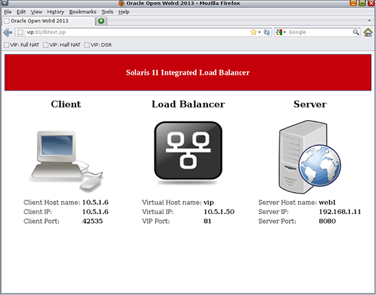
Figure 9. Results of test done in half-NAT mode.
Test with Apache JMeter
- Launch Apache JMeter by double-clicking its
 icon on the desktop.
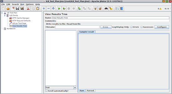
Figure 10. Apache JMeter.
Next, we will use the JMeter test file you created earlier,
ILB_Test_Plan.jmx, in which five clients are simulated with each sending four requests to the load balancer. - To start the test, open the
ILB_Test_Plan.jmxfile by clicking the icon.
icon.
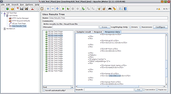
Figure 11. Running the Apache JMeter test.
- To see the results, click View Results Tree in the left frame. Then choose HTML in the list box at the bottom of the middle frame, and then click the Response data tab in the right frame.
The middle frame lists the 20 requests sent to the load balancer, and by clicking each, you will see in the Response data tab which back-end server actually served the request. There should be as many requests served by
web1as byweb2.To clear the results before a new test is run, click the
 icon.
icon.
Create and Test a Customized Health Check Script
All following commands are executed in the ilb-zone zone.
- Check the status of the back-end servers according to the health check. Both back-end servers should be reported as alive.
[root@ilb-zone]# ilbadm show-hc-res RULENAME HCNAME SERVERID STATUS FAIL LAST NEXT RTT web_rule_fn web_hc _web_sg_2.0 alive 0 12:40:14 12:40:25 4628 web_rule_fn web_hc _web_sg_2.1 alive 0 12:40:14 12:40:18 2120 web_rule_hn web_hc _web_sg_2.0 alive 0 12:40:09 12:40:18 669 web_rule_hn web_hc _web_sg_2.1 alive 0 12:40:10 12:40:21 563 - Stop the Tomcat server on
web1:[root@ilb-zone]# ssh root@web1-priv svcadm disable tomcat6 [root@ilb-zone]# ssh root@web1-priv svcs tomcat6 - Check again the status of the
web1back-end server.Although the Tomcat server is stopped, the health check is not aware of this and keeps web1 as a potential back-end server. The problem with the current health check is that it is a simple ping on the server hosting Tomcat. As long as the server responds to the ping, health check considers the server alive.
[root@ilb-zone]# ilbadm show-hc-res RULENAME HCNAME SERVERID STATUS FAIL LAST NEXT RTT web_rule_fn web_hc _web_sg_2.0 alive 0 12:50:48 12:50:53 570 web_rule_fn web_hc _web_sg_2.1 alive 0 12:50:43 12:50:53 712 web_rule_hn web_hc _web_sg_2.0 alive 0 12:50:43 12:50:54 671 web_rule_hn web_hc _web_sg_2.1 alive 0 12:50:44 12:50:55 773 - Create a custom health check script.
To avoid the problem exposed above, a more application-aware health check script should be used. Create a file called
/var/web_hc.shwith the content shown in Listing 6. This script uses a simplecurlcommand to check whether the web server returns a response starting with the string"<meta". If it does, we are assured that the web server is running.#!/bin/bash result=`curl -s http://$2:8080` if [ "${result:0:5}" = "<meta" ]; then echo 0 else echo -1 fiListing 6. Content for the custom health check script.
Note: The health check custom script must be executable, so run the following command:
[root@ilb-zone]# chmod 755 /var/web_hc.sh - Delete the current health check and delete the rules that use that health check, since updating health checks and rules is currently not supported.
[root@ilb-zone]# ilbadm delete-rule web_rule_fn [root@ilb-zone]# ilbadm delete-rule web_rule_hn [root@ilb-zone]# ilbadm delete-hc web_hc - Now re-create the health check using the custom script. Also re-create the rules.
[root@ilb-zone]# ilbadm create-hc -h hc-timeout=3,hc-count=2,hc-interval=8,hc-test=/var/web_hc.sh web_hc [root@ilb-zone]# ilbadm create-rule -e -i vip=10.5.1.50,port=80 -m lbalg=rr,type=NAT,proxy-src=192.168.1.10 -h hc-name=web_hc,hc-port=8080 -o servergroup=web_sg_2 web_rule_fn [root@ilb-zone]# ilbadm create-rule -e -i vip=10.5.1.50,port=81 -m lbalg=rr,type=HALF-NAT -h hc-name=web_hc,hc-port=8080 -o servergroup=web_sg_2 web_rule_hn - Now check the status of the
web1back-end server. This time, the health check works as expected, andweb1is reported as dead. No requests will be sent toweb1anymore.[root@ilb-zone]# ilbadm show-hc-res RULENAME HCNAME SERVERID STATUS FAIL LAST NEXT RTT web_rule_fn web_hc _web_sg_2.0 dead 3 12:55:07 12:55:16 586 web_rule_fn web_hc _web_sg_2.1 alive 0 12:55:08 12:55:18 558 web_rule_hn web_hc _web_sg_2.0 dead 2 12:55:02 12:55:14 524 web_rule_hn web_hc _web_sg_2.1 alive 0 12:55:06 12:55:14 511 - Using Firefox, test to check that only
web2responds. - Restart Tomcat on
web1and test again to check that the load balancer will send requests toweb1again.[root@ilb-zone]# ssh root@web1-priv svcadm enable tomcat6 [root@ilb-zone]# ssh root@web1-priv svcs tomcat6
Configure and Test the Load Balancer in DSR Mode
In DSR mode, the back-end servers respond directly without going through the load balancer, so they should have a route to the client.
Prepare the Web Zones
To keep things simple, in this exercise we will simply connect the web zones to the public network (10.5.1.0).
- Log in to
web1from the global zone:[root@kafka]# zlogin web1 [Connected to zone 'web1' pts/3] Oracle Corporation SunOS 5.11 11.1 September 2012 You have new mail. [root@web1]# - Prior to starting the exercises, you configured the zones to have two IP interfaces, but one interface was not configured. Now, configure that interface to connect to our public network:
[root@web1]# ipadm create-ip web1_1 [root@web1]# ipadm create-addr -T static -a 10.5.1.11/24 web1_1/v4 [root@web1]# ipadm show-addr - Define the default route to the public network:
[root@web1]# route add default 10.5.1.6 -ifp web1_1 - Now configure the
web1zone so that it responds to requests sent to the VIP address (10.5.1.50):[root@web1]# ipadm create-vni vni0 [root@web1]# ipadm create-addr -T static -a 10.5.1.50/24 vni0/v4vip - Perform the same operations in zones
web2andweb3by adapting the parameters for the IP interface name and the IP address accordingly:[root@web2]# ipadm create-ip web2_1 [root@web2]# ipadm create-addr -T static -a 10.5.1.12/24 web2_1/v4 [root@web2]# ipadm show-addr [root@web2]# route add default 10.5.1.6 -ifp web2_1 [root@web2]# ipadm create-vni vni0 [root@web2]# ipadm create-addr -T static -a 10.5.1.50/24 vni0/v4vip [root@web3]# ipadm create-ip web3_1 [root@web3]# ipadm create-addr -T static -a 10.5.1.13/24 web3_1/v4 [root@web3]# ipadm show-addr [root@web3]# route add default 10.5.1.6 -ifp web3_1 [root@web3]# ipadm create-vni vni0 [root@web3]# ipadm create-addr -T static -a 10.5.1.50/24 vni0/v4vip
Configure a DSR Load-Balancing Rule in ilb-zone
- Create a new server group:
web_sg_1. The back-end servers are actually the same (web1andweb2), but this time we are using their public IP addresses.[root@ilb-zone]# ilbadm create-sg -s servers=web1,web2 web_sg_1 - Add a load-balancing rule in DSR mode on port 8080:
[root@ilb-zone]# ilbadm create-rule -e -i vip=10.5.1.50,port=8080 -m lbalg=hash-ip-port,type=DSR -h hc-name=web_hc,hc-port=8080 -o servergroup=web_sg_1 web_rule_dsr - Test DSR mode with Firefox using the URL
http://vip:8080/ilbtest.jsp.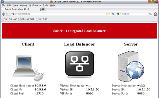
Figure 12. Results of testing a load-balancing rule in DSR mode.
Refresh the page several times (pressing the Shift key to prevent caching).
Note: In DSR mode, we are no longer using the round-robin algorithm; instead we are using the "source IP, port hash" algorithm. This means that we are not assured that each refresh will send requests to a different back-end server. So if you see the same server responding several times in a row, this is normal behavior.
Add a Server to and Remove a Server from the Back-End Server Group
In this exercise, we will first add the third web server to our server group and then remove one existing server.
Add web3 to the web_sg_1 Server Group
- Add
web3to theweb_sg_1server group:[root@ilb-zone]# ilbadm add-server -s server=web3 web_sg_1 - Test DSR mode with Firefox using the URL
http://vip:8080/ilbtest.jsp.You should now see
web3responding to clients if you refresh the page several times.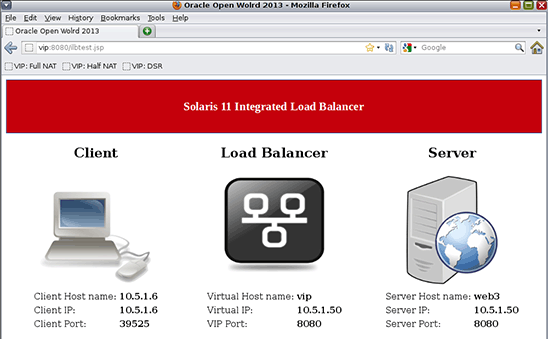
Figure 13. Test adding a server to the server group.
Remove a Server from the web_sg_1 Server Group
- Remove
web1from theweb_sg_1server group:[root@ilb-zone]# ilbadm remove-server -s server=_web_sg_1.0 web_sg_1 - Test DSR mode with Firefox using the URL
http://vip:8080/ilbtest.jsp.You should now see that
web1is no longer responding to client requests and onlyweb2andweb3respond to client requests.
This ends our lab, but there is still much more to know about the Integrated Load Balancer. To get a deeper understanding of the subject, refer to the Oracle documentation (links are provided in the "See Also" section) and to Appendix A.
Appendix A: More About Network Virtualization and the Integrated Load Balancer
Oracle Solaris Network Virtualization
The Integrated Load Balancer is part of a much bigger picture. Oracle Solaris 11 network virtualization allows you to build any physical network topology inside the Oracle Solaris operating system, including virtual network cards (VNICs), virtual switches (vSwitches), and more-sophisticated network components (for example, load balancers, routers, and firewalls).
Benefits of network virtualization include reduced infrastructure costs and increased speed of infrastructure deployment, since all the network building blocks are based on software, not on hardware.

Figure 14. Example of infrastructure consolidation achieved through network virtualization.
Integrated Load Balancer Features and Capabilities
The Integrated Load Balancer does the following:
- Provides layer 3 and layer 4 load-balancing capabilities for Oracle Solaris 11 on SPARC and x86 systems
- Intercepts incoming requests sent from clients to a virtual IP address, and decides which back-end server should handle the request based on load-balancing rules
- Provides a command-line interface for administration and the
libilblibrary, which enables third-party vendors to create software that uses the Integrated Load Balancer functionality - Supports stateless Direct Server Return (DSR) and Network Address Translation (NAT) modes of operation for IPv4 and IPv6
- Provides server monitoring capabilities through health checks
The main features of the Integrated Load Balancer include the following:
- Ability to add or remove servers from a server group without interrupting service (NAT)
- Session persistence (stickiness)
- Connection draining
- Load-balancing of TCP and UDP ports
- Ability to specify independent ports for virtual services within the same server group
- Ability to load balance a simple port range
- Port range shifting and collapsing
Integrated Load Balancer Operation Modes
The Integrated Load Balancer provides three operation modes: DSR mode, half-NAT mode, and full-NAT mode.
Figure 15 shows DSR mode. The advantages of DSR mode are that it provides better performance than NAT mode, and it provides full transparency between the server and the client.
Disadvantages of DSR mode include the following:
- The back-end server must respond to both its own IP address (for health checks) and to the virtual IP address (for load-balanced traffic).
- Because it maintains no connection state, adding or removing servers will cause connection disruption.
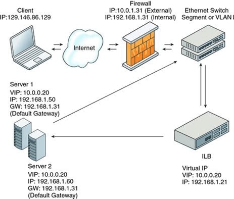
Figure 15. DSR mode.
Figure 16 shows NAT mode. The following are the advantages of NAT mode:
- It works with all back-end servers by changing the default gateway to point to the load balancer.
- Because the load balancer maintains the connection state, adding or removing servers without connection disruption is possible.
Disadvantages of NAT are that it provides slower performance than DSR and all the back-end servers must use the load balancer as a default gateway.

Figure 16. NAT mode.
Integrated Load Balancer Algorithms
The following algorithms control traffic distribution and server selection:
- Round robin: Requests are assigned to a server group on a rotating basis.
- Source IP hash: A server is selected based on the hash value of the source IP address of the incoming request.
- Source IP, port hash: A server is selected based on the hash value of the source IP address and the source port of the incoming request.
- Source IP, VIP hash: A server is selected based on the hash value of the source IP address and the destination IP address of the incoming request.
See Also
In the Oracle Solaris 11.1 Information Library, you will find the documentation for the Integrated Load Balancer in the Managing Oracle Solaris 11.1 Network Performance manual.

Figure 17. Documentation for the Integrated Load Balancer.
Here are additional resources:
- Download Oracle Solaris 11
- Access Oracle Solaris 11 product documentation
- Access all Oracle Solaris 11 how-to articles
- Learn more with Oracle Solaris 11 training and support
- See the official Oracle Solaris blog
- Check out The Observatory blog for Oracle Solaris tips and tricks
- Follow Oracle Solaris on Facebook and Twitter
About the Author
Amir Javanshir is a Principal Software Engineer working in Oracle's global ISV Engineering team where he focuses on driving technology adoption and integration of Oracle systems technologies by strategic independent software vendors (ISVs). He is currently specializing in virtualization, cloud computing, and enterprise architecture (EA). Amir joined Oracle in 2010 as part of the Sun Microsystems acquisition.
Revision 1.0, 02/12/2014