Re-engineering Your Database Using Oracle SQL Developer Data Modeler 3.1
Overview
- Import two tables (EMPLOYEES and DEPARTMENTS) from the HR schema into SQL Developer Data Modeler.
- Add a new table (PROJECTS), join it to the DEPARTMENTS table and create a new column (MOBILE_NUMBER) in the EMPLOYEES table.
- Reverse engineer the relational model to a logical model
- Modify the model by creating a new Entity with Attributes and relations.
- Synchronize the logical with the Relational Model
- Generate the DLL with the changes you made
- Have installed Oracle SQL Developer Data Modeler Release 3.1
- Have access to an Oracle Database 11g database that has the sample schema installed.
Purpose
This tutorial covers how to make changes to your database using the relational model in Oracle SQL developer Data Modeler Release 3.1.
Time to Complete
Approximately 60 minutes
Introduction
Oracle SQL Developer Data Modeler is a tool that enables you to diagrammatically display your database objects, make changes, and update the schema based on the changes quickly and easily. It is a standalone, independent product available for download and free use from OTN.
You can import from and export to a variety of sources and targets. You also have a variety of formatting options and can validate the models through a predefined set of Design Rules. Using this tool, you can connect to any Oracle supported database.
Scenario
In this tutorial, you use Oracle SQL Developer Data Modeler Release 3.1 to perform the following:
Prerequisites
Before starting this tutorial, you should:
Importing Tables from HR Schema
In this topic, you will create a connection to the HR schema. Using this connection, you import the EMPLOYEES and DEPARTMENTS tables into SQL Developer Data Modeler:
Double-click the Oracle SQL Developer Data Modeler icon from the Desktop.
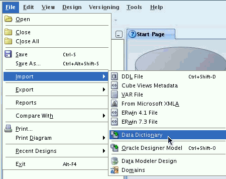
To import tables from the data dictionary, select File > Import > Data Dictionary.
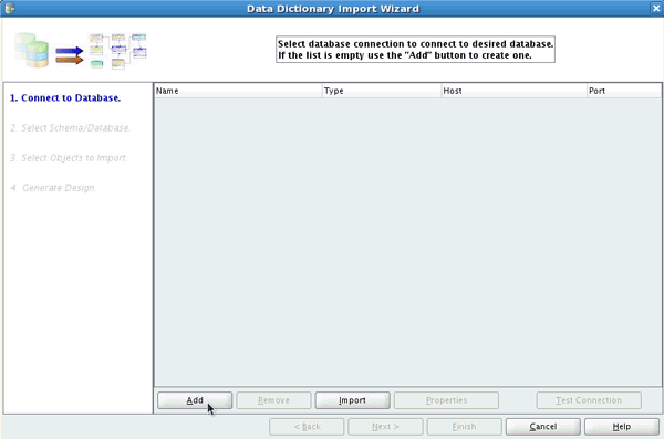
The Data Dictionary Import Wizard opens. To create a connection to the database, click Add.
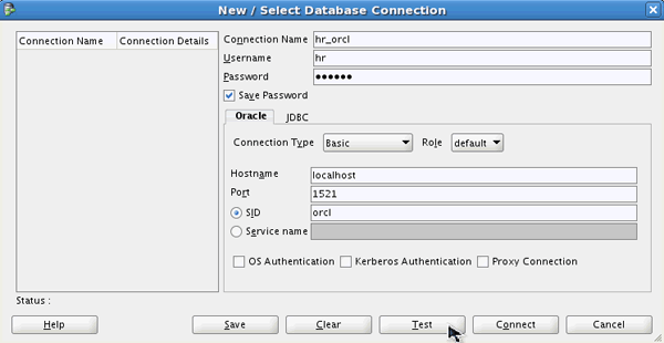
A New / Update Database Connection dialog opens. Enter the connection details as follows and click Test.
Connection Name: hr_orcl
User Name: hr
Password: oracle
Hostname: localhost
SID: orcl
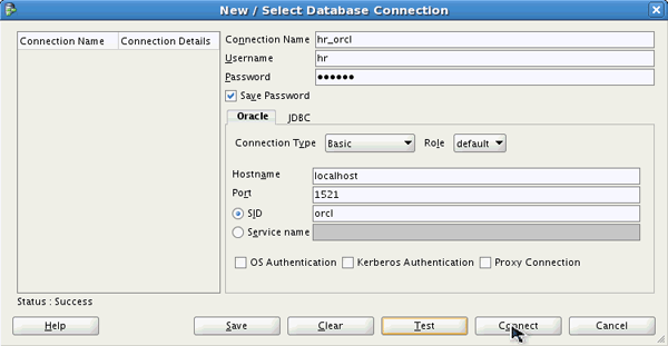
The status is Success. Click Connect.
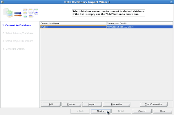
In the Data Dictionary Import Wizard, select the hr_orcl connection you just created and click Next.
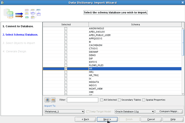
You want to import only the HR schema. Select the HR schema and click Next.
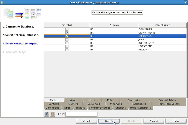
Select the DEPARTMENTS and EMPLOYEES tables and click Next.
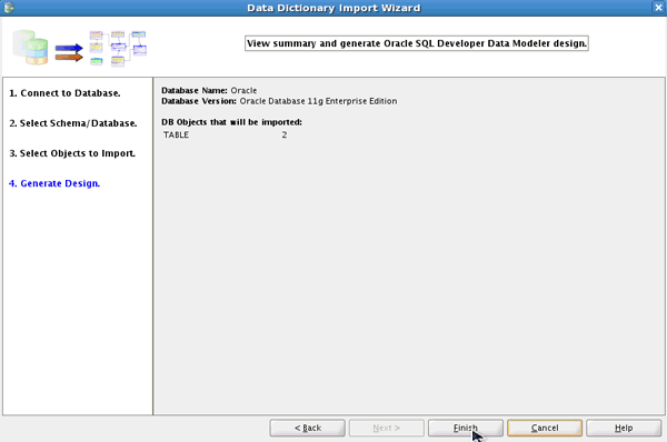
Click Finish to generate the design.
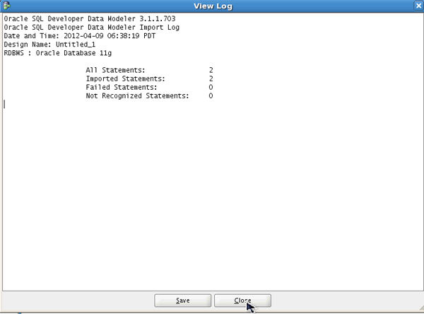
Review the log file created and click Close.
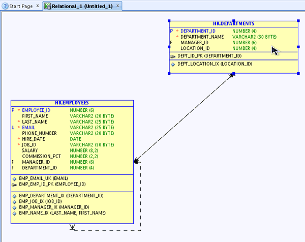
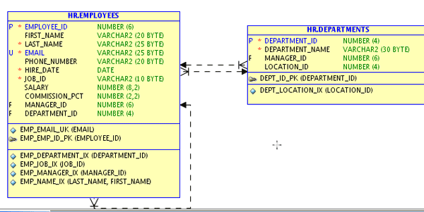
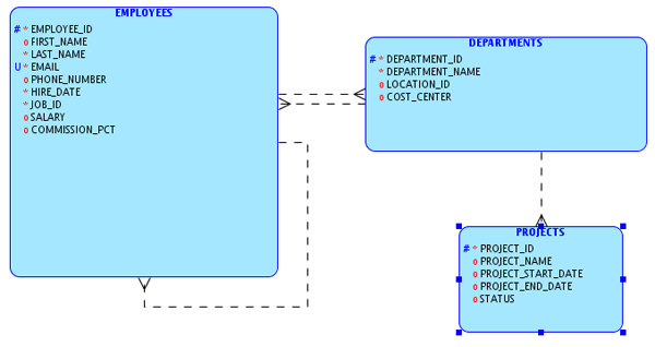
The EMPLOYEES and DEPARTMENTS tables are successfully imported into a relational model within SQL Developer Data Modeler. If the tables do not line up correctly, you can drag it to where you want the object to go.
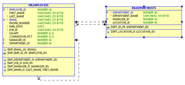
The table is repositioned as well as the relations. In the next topic, you review the physical model which is automatically created when you import the objects from the data dictionary.
Reviewing the Physical Model
In this topic, you review the physical model that is automatically created when you import the objects from the data dictionary.
In the Nagivation Browser, expand Relational Models > Relational_1.
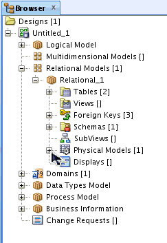
You see that there is one Physical Model. Expand Physical Models > Oracle Database 11g.
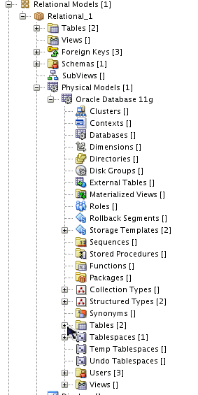
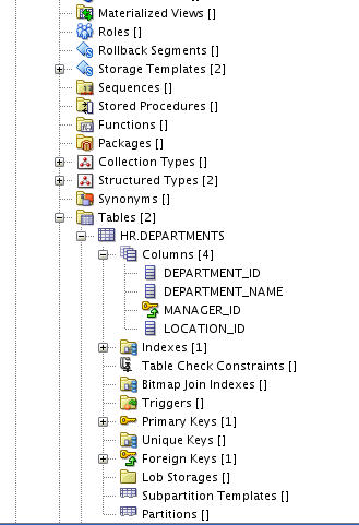
Expand Tables > HR.DEPARTMENTS > Columns. Review the list. Note the other objects that are available in the Physical Model. In the next section, you create a table in the Relational model.
Creating a New Table
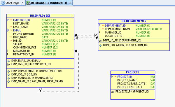
In this topic, you create a PROJECTS table. The PROJECTS table has four columns: PROJECT_ID, PROJECT_NAME, PROJECT_START_DATE, and PROJECT_END_DATE.
Click the New Table icon ( ) from the Oracle SQL Developer Data Modeler toolbar.
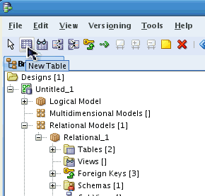
Click the white space of the diagram.
A Table Properties dialog opens. Enter PROJECTS for Name and click Columns on the left-navigator.
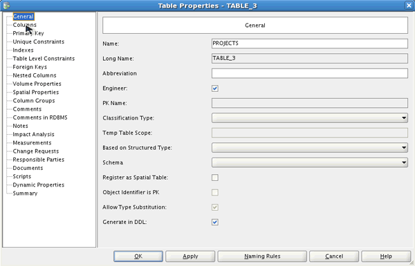
To add a column, click the Create Column icon ( ).
).
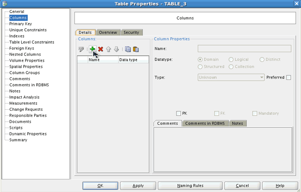
Enter PROJECT_ID for Name. Select Logical for Datatype and NUMERIC for Type.
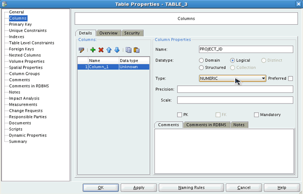
Enter 6 for Precision. You want the PROJECT_ID column to be the Primary Key. Select the PK checkbox and click the Create Column icon to add another column.
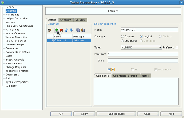
Enter PROJECT_NAME for Name. Select Logical for Datatype and VARCHAR for Type.
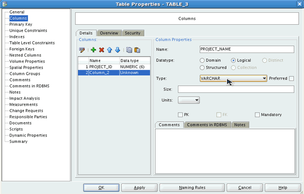
Enter 100 for Size and click the Create Column icon to add another column.
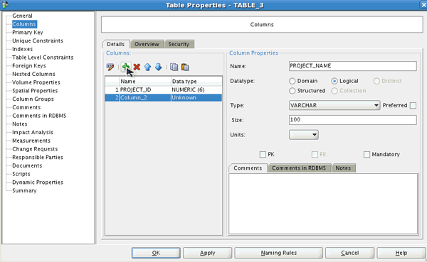
Enter PROJECT_START_DATE for Name. Select Logical for Datatype and Date for Type. Click the Create Column icon to add another column.
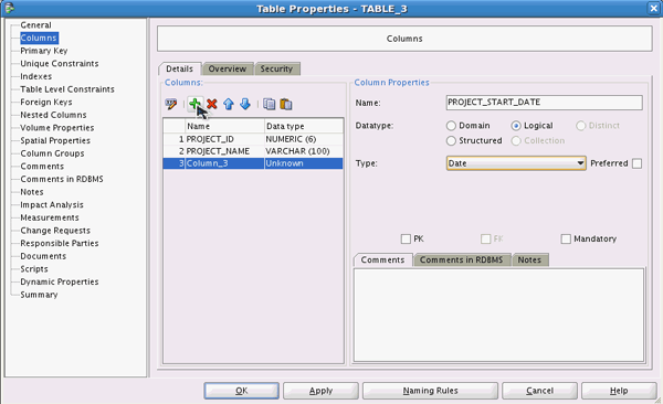
Enter PROJECT_END_DATE for Name. Select Logical for Datatype and Date for Type. Click OK to create the table.
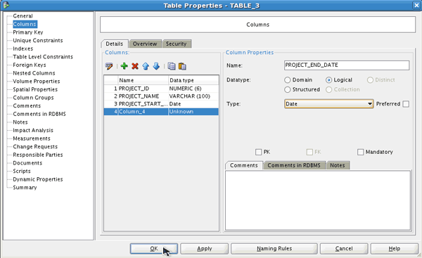
The table is created successfully.
Joining the New Table to the Existing Table
In this topic, you create a foreign key between the PROJECTS table and the DEPARTMENTS tables.
Click the New FK Relation icon ( ) from the toolbar.
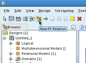
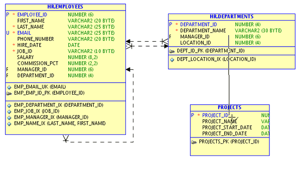
To create a foreign key in the PROJECTS table, click the DEPARTMENTS table and then click the PROJECTS table.
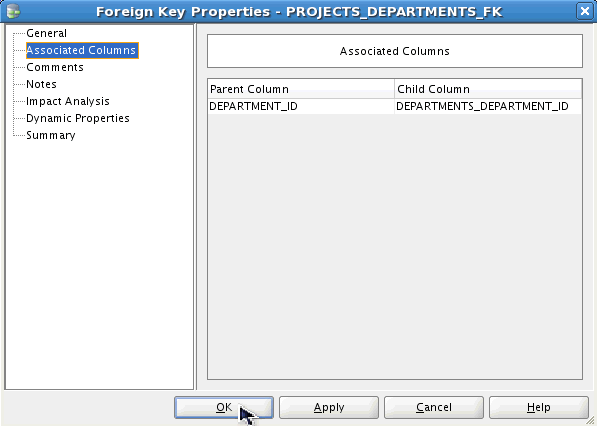
A Foreign Key Properties dialog opens. Select Associated Columns from the left-navigator.
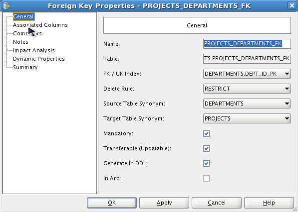
Confirm that DEPARTMENTS_DEPARTMENT_ID is selected for Child Column and click OK.
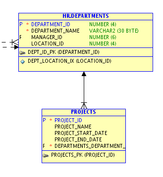
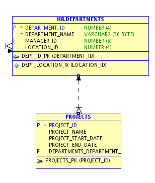
Select the Arrow  in the toolbar. The FK Relation is created. The 'F' against DEPARTMENTS_DEPARTMENT_ID in the PROJECTS table identifies the column as a foreign key.
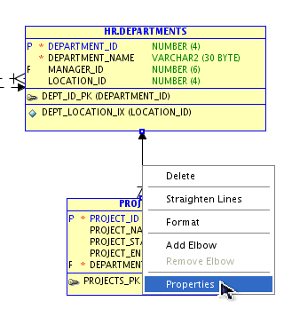
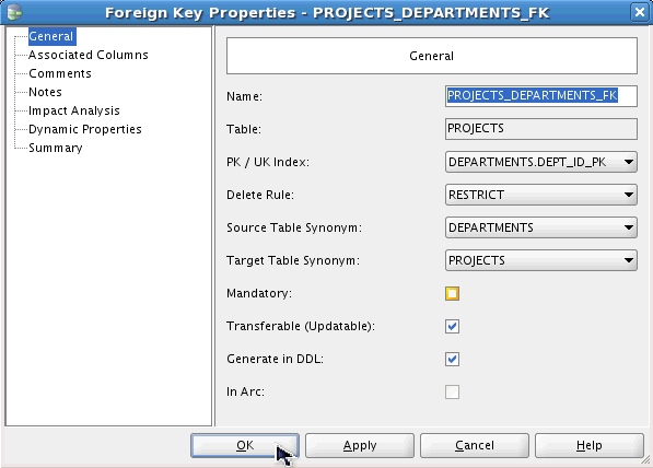
To make the FK optional, right-click on the line joining the two tables and select Properties.
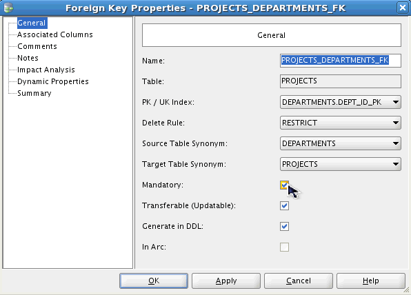
Deselect the Mandatory checkbox. and click OK.
Click OK.
Click Yes.
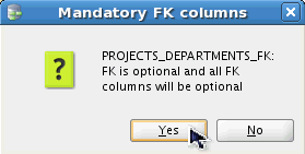
The FK is now optional. This means that you can have a Project without a Department.
Modifying an Existing Table
In this topic, you add the COST_CENTER column to the DEPARTMENTS table.
In the diagram, double-click the DEPARTMENTS table.
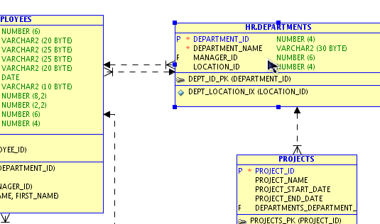
Select the Columns property from the left-navigator.
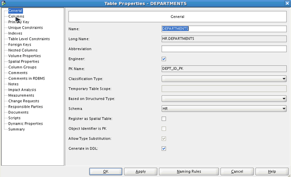
To create a new column, click the Create Column icon.
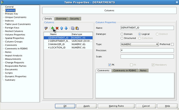
Enter COST_CENTER for Name, select Logical for Datatype, VARCHAR for Type and enter 25 for Size. Then click OK to create the column..
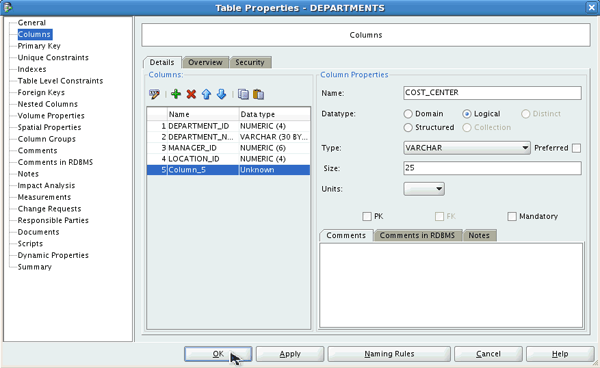
The COST_CENTER column is successfully created in the DEPARTMENTS table.
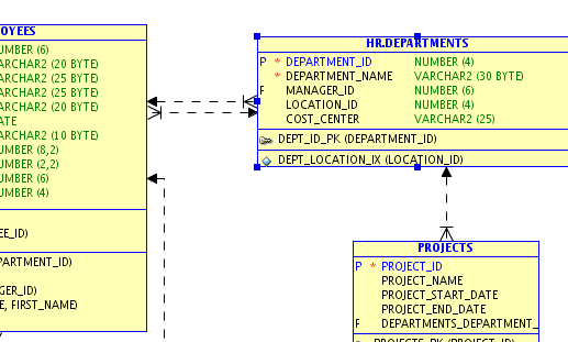
Reverse Engineering the Relational Model to Create a Logical Model
In this topic, you reverse engineer the relational model to create a logical model.
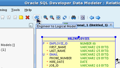
Select the Engineer to Logical Model icon in the toolbar.
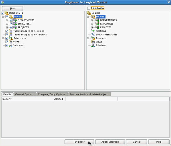
The Engineer to Logical Model window appears. Expand Tables. Notice the entities that will be created in the Logical Model. Click Engineer.
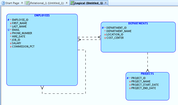
The Logical Model is displayed. Review the entities and attributes. The diagram for the Logical Model is called the Entity Relationship Diagram (ERD).
Modifying the Logical Model
In this topic, you modify the logical model.
You want to add some attributes to the PROJECTS entity. Double-click the PROJECTS entity.
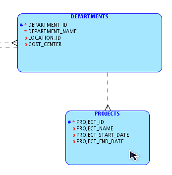
Select the Attributes property in the left navigator.
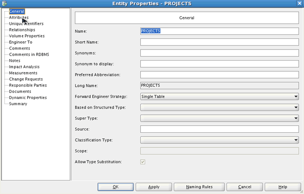
Select the '+' add attributes icon.
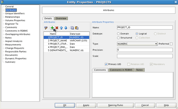
Enter STATUS for Name, select Logical for Datatype, select VARCHAR for the Type, and enter 30 for Size. Select the DEPARTMENT_DEPARTMENT_ID attribute from the list.
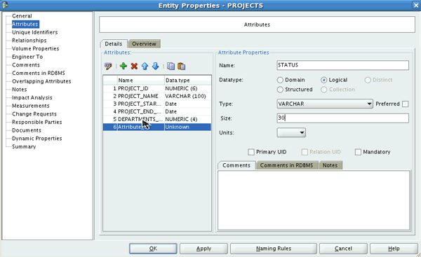
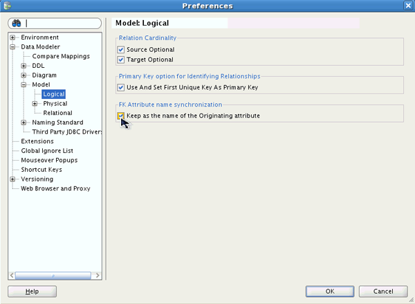
This attribute is shown as a result of the relation between the DEPARTMENTS and PROJECTS entities. Notice that you can not change the name of the attribute. You do want to change the name so you need to change one of the preference settings. Click OK.
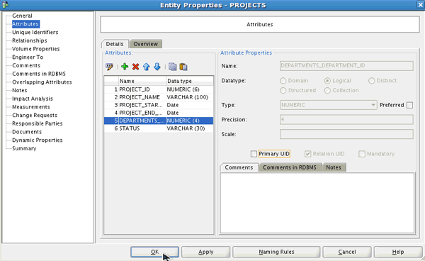
Notice that the STATUS attribute was added to the PROJECTS entity and that the DEPARTMENT relation is not displayed on the diagram. Currently you are viewing the Barker notation which does not show the relation attributes. Later in this section you change the notation to the Bachman notation which does display the relation attributes in the diagram.
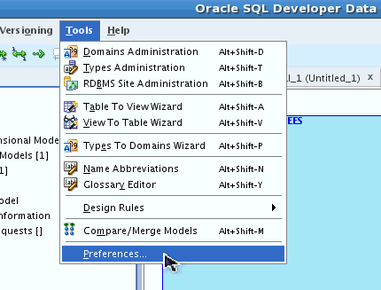
You want to change the default so that you can change the name of the relation attribute. Select Tools > Preferences...
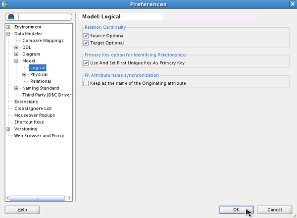
Expand Data Modeler > Model and select Logical. Deselect the checkbox for Keep as the name of the Originating attribute.
Click OK.
Double-click the PROJECTS entity again.
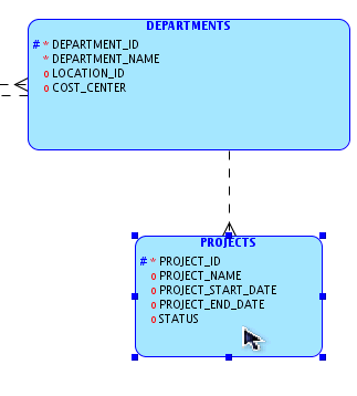
Select the Attributes property.
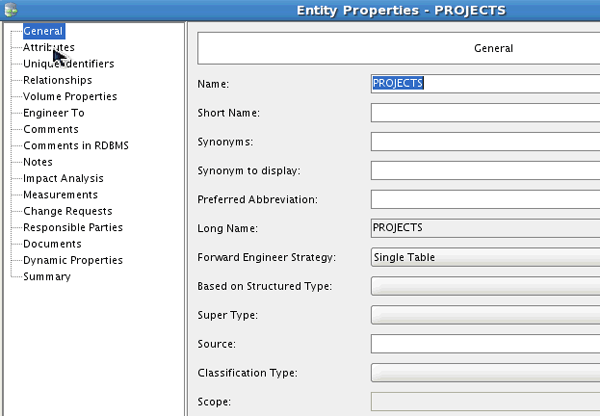
Select the DEPARTMENT_DEPARTMENT_ID attribute from the list.
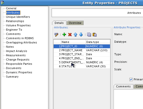
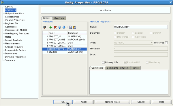
Notice that the Name is now enabled so you can change its name. Change the name to PROJECT_DEPT and click OK.
Change the notation to the Bachman notation. Right-click the white space in the diagram to show the context window. Select Bachman Notation.
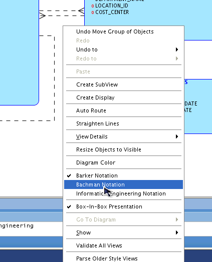
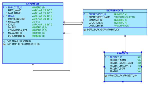
Notice the notation has changed. You now see the relation attributes (noted with the 'F') as well as the Primary Key attributes. The '*' before each attribute indicates that it is a mandatory attribute.
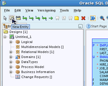
You want to add another entity to the Logical Model. Select the New Entity icon in the toolbar.
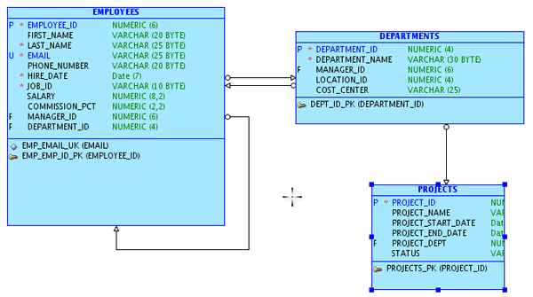
Click the white space of the diagram.
Enter TASKS for Name and select the Attributes property.
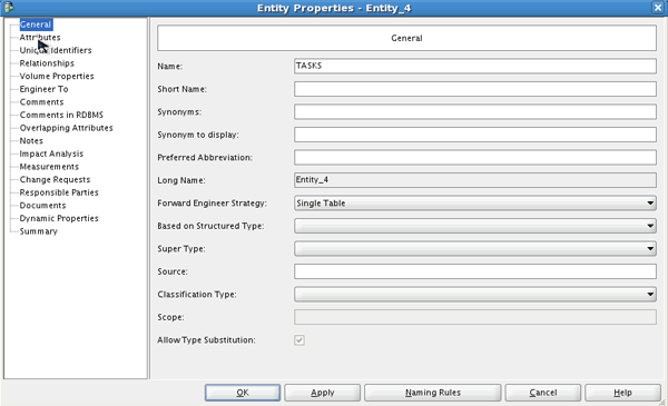
Select the '+' add attribute icon.
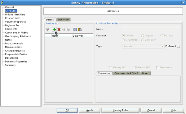
Enter TASK_ID for Name, Select Logical for Datatype, select NUMERIC for Type, enter 6 for Precision and select the Primary UID checkbox. Then select the '+' add attribute icon to add another attribute.
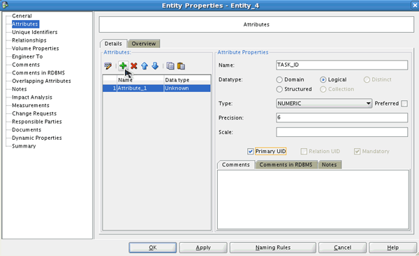
Enter TASK_NAME for Name, select Logical for Datatype, select VARCHAR for Type and enter 255 for Size and click the create attribute icon.
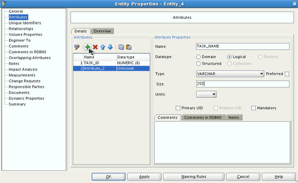
Enter COST for Name, select Logical for Datatype, select NUMERIC for Type and enter 6 for Size and click the create attribute icon.
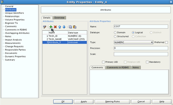
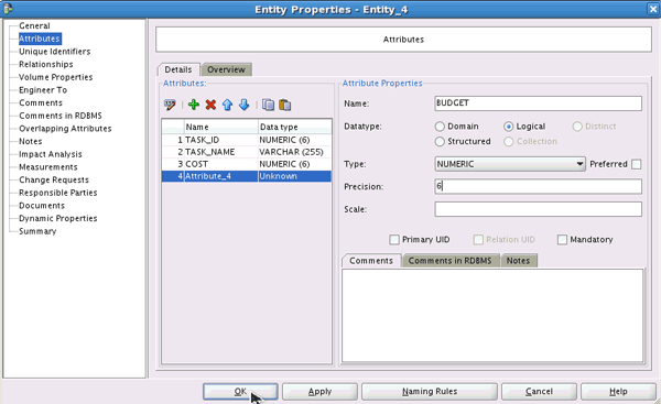
Enter BUDGET for Name, select Logical for Datatype, select NUMERIC for Type and enter 6 for Size and click OK to create the entity and its attributes.
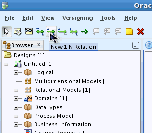
You want to create two relations between the EMPLOYEES and TASKS, and the PROJECTS and TASKS entities. Select the New 1:N Relation icon in the toolbar.
Select the EMPLOYEES entity and then select the TASKS entity.
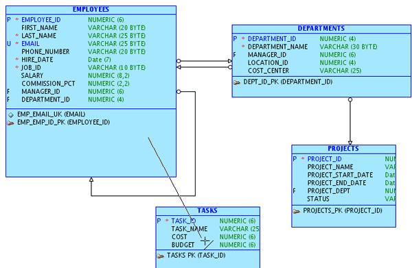
Click OK to create the Relation.
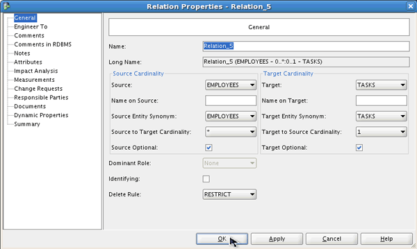
Now you can create the second relation. Click the PROJECTS entity and then click the TASKS entity.
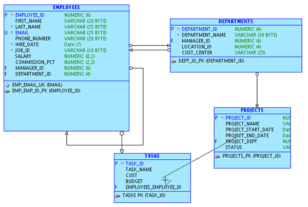
Click OK to create the relation.
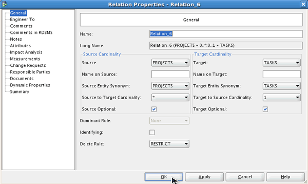
The relation is displayed. Click the  in the toolbar. You want to change the name of the relation in the TASKS entity. Double-click the TASKS entity.
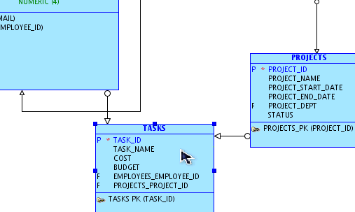
Select the Attributes property.
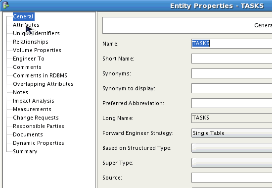
Select the EMPLOYEES_EMPLOYEE_ID attribute from the list.
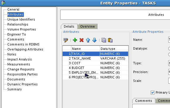
Change the name to ASSIGNED_TO and then select the PROJECTS_PROJECT_ID attribute from the list.
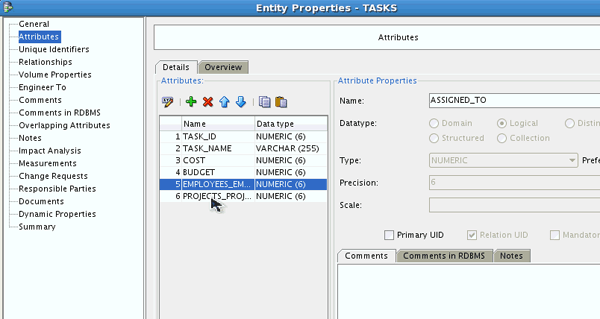
Change the name to PROJECT_ID and click OK.
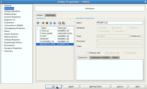
Changes to your logical model are complete. In the next topic, you synchronize your changes with the relational model.
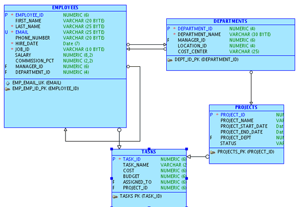
Synchronizing the Logical Model with the Relational Model
In this topic, you synchronize the logical model with the relational model.
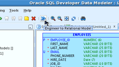
Select the Engineer to Relational Model icon.
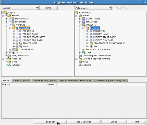
The Engineer to Relational Model window appears. Expand Entities > PROJECTS > Attributes. Note the differences. Click Engineer.
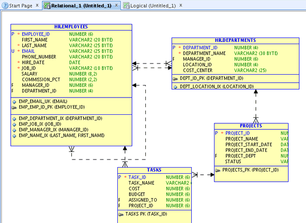
Note the new STATUS column, the name change PROJECT_DEPT for the foreign key, and the new TASKS table.
Generating the DDL to Update the Database
Now that your models are complete you want to synchronize the data dictionary with the model and generate the DDL.
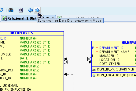
Select the Synchronize Data Dictionary with Model icon in the toolbar.
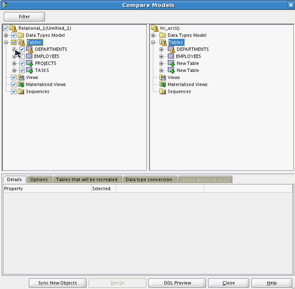
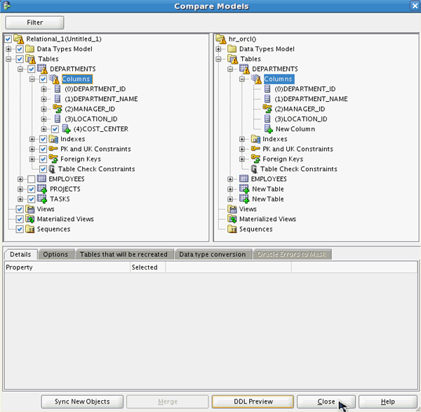
The Compare Models dialog opens. Nodes where changes have been made are marked with a triangle symbol ( ). In this case, the tables node is marked. Expand the Tables node to see the new tables for PROJECTS and TASKS. Notice that the DEPARTMENTS table has changed.
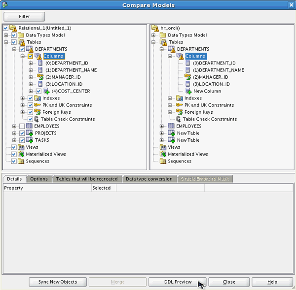
Expand DEPARTMENTS > Columns. The COST_CENTER column will be added. Click DDL Preview.
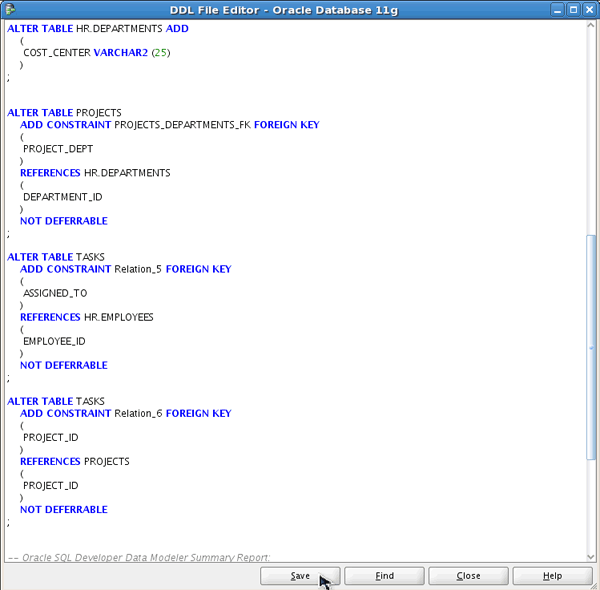
The code generated is displayed. Review the CREATE and ALTER statements. Note that the PROJECTS and TASKS tables will be created and altered to create the Primary Keys. Scroll down to the bottom of the page.
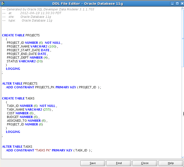
On this page, you see the new column, foreign key constraints. Click Save.
Note you can execute this script in SQL Developer to update the database. You will do that in the next tutorial.
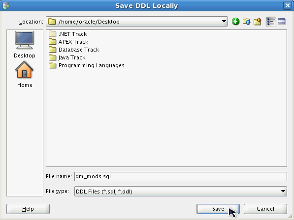
Save the file to your Desktop. Click Save.
Click Close to close the Compare Models window.
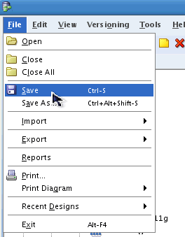
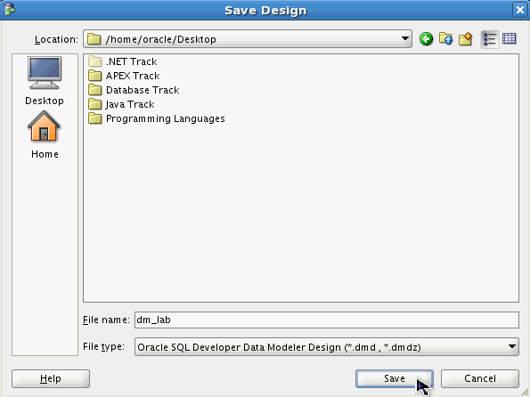
You want to save your model. Select File > Save.
Save the file to your Desktop. Click Save.
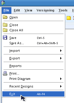
Clock SQL Developer Data Modeler. Select File > Exit.
Summary
- Import tables from data dictionary
- Review the physical model
- Create new table and join to an existing table
- Create new column in an existing table
- Reverse engineer to create the logical model
- Modify the logical model
- Synchronize the logical model with the relational model
- Generate DDL to update database
- The solutions for this tutorial are located in the files.zip file.
- Oracle SQL Developer Data Modeler homepage
- Oracle SQL Developer homepage on OTN.
- Oracle Data Modeling and Relational Database Design course.
- Oracle Learning Library
- Oracle University
In this tutorial, you have learned how to:
Resources
To help navigate this Oracle by Example, note the following:
- Hiding Header Buttons:
- Click the Title to hide the buttons in the header. To show the buttons again, simply click the Title again.
- Topic List Button:
- A list of all the topics. Click one of the topics to navigate to that section.
- Expand/Collapse All Topics:
- To show/hide all the detail for all the sections. By default, all topics are collapsed
- Show/Hide All Images:
- To show/hide all the screenshots. By default, all images are displayed.
- Print:
- To print the content. The content currently displayed or hidden will be printed.
To navigate to a particular section in this tutorial, select the topic from the list.