Ethernet Network Switch Certification
The requirements and configurations needed to certify Ethernet Network Switch Certification are different from that of certifying other components with Oracle HCTS. Hence, this chapter is dedicated only to Ethernet Network Switch and the procedure to certify them using Oracle HCTS.
This chapter covers the following sections:
Requirements for Certifying Ethernet Network Switch
Certifying the Ethernet Network Switch has the following requirements:
The user has to setup the HCTS System Under Test (SUT) and HCTS Test Manager (TM) in manual mode. For more information, see Appendix C, Manual Network Configuration.
Ensure that the ipkg://solaris/benchmark/iperf package is available on both SUT and TM.
Ensure that the switch has been setup properly before running the test cases.
There are four test cases for certifying a network switch: Link Speed, Jumbo Frame, Port Mirroring, and Link Aggregation. The four test cases are independent and each has its own test result. The user has to run these test cases separately and submit all network switch test results for an audit.
The user has to define the parameters for each test case in the /opt/SUNWhcts/etc/switch.conf configuration file. The user also has to add two different records for each test case in this file. A record is used to provide parameters for the test case.
To test the Link Speed and Jumbo Frame test cases, SUT must have at least 3 NIC ports and TM must have at least 2 NIC ports.
To test the Port Mirroring and Link Aggregation test cases, SUT must have at least 5 NIC ports and TM must have at least 2 NIC ports.
Link Speed Test Case
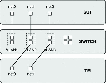
The Link Speed test case is designed to verify the data transmit/receive functionality on different link speed modes supported by the switch. The network card speed of SUT and TM need to be higher than the switch ports they are connected to.
The Link Speed test case running environment can be schematically represented as shown in the following figure.
Figure 6-1 Link Speed Test Case
 To Set Up Link Speed Test Case
- Configure the switch by executing the following steps.
- Setup three VLANs: VLAN1, VLAN2 and VLAN3 on the switch, and ensure
that each VLAN includes two switch ports.
- Assign an IP address to VLAN1. Select one switch port of VLAN1 as
administrator port and connect it to SUT.
- Enable Full-duplex and Auto-Negotiation functions for each port in VLAN2 and VLAN3.
- Configure the Test Manager by executing the following steps.
- Setup the TM in manual mode. Select two links NET0 and NET1
as test links, and assign the IP address to each link by
the TM.
- Connect NET0 to the port of VLAN2, and NET1 to the port of
VLAN3.
- Configure the System Under Test by executing the following steps.
- Setup the SUT in manual mode. Select three links NET0, NET1 and
NET2 as test links, and assign the IP address to the each link
by the SUT.
- Save the test type, NET1 and NET2 IP address of SUT, NET0 and
NET1 IP address of TM into /opt/SUNWhcts/etc/switch.conf file respectively.
- Connect NET0 to the port of VLAN1, NET1 to the port of
VLAN2, NET2 to the port of VLAN3.
- Setup three VLANs: VLAN1, VLAN2 and VLAN3 on the switch, and ensure that each VLAN includes two switch ports.
- Assign an IP address to VLAN1. Select one switch port of VLAN1 as administrator port and connect it to SUT.
- Enable Full-duplex and Auto-Negotiation functions for each port in VLAN2 and VLAN3.
- Setup the TM in manual mode. Select two links NET0 and NET1 as test links, and assign the IP address to each link by the TM.
- Connect NET0 to the port of VLAN2, and NET1 to the port of VLAN3.
- Setup the SUT in manual mode. Select three links NET0, NET1 and NET2 as test links, and assign the IP address to the each link by the SUT.
- Save the test type, NET1 and NET2 IP address of SUT, NET0 and NET1 IP address of TM into /opt/SUNWhcts/etc/switch.conf file respectively.
- Connect NET0 to the port of VLAN1, NET1 to the port of VLAN2, NET2 to the port of VLAN3.
Example 6-1
The following example displays how to set up Link Speed test case.
For a switch, there are three VLANS: VLAN1, VLAN2 and VLAN3:
      . show vlan
      VLAN Name                         Status    Ports
      ---- -------------------------------- --------- ------------

      5    VLAN1                       active    Gi1/1, Gi1/2
      30   VLAN2                       active    Gi1/11, Gi1/12
      40   VLAN3                       active    Gi1/21, Gi1/22
      The switch administration port IP address for VLAN1:

      .show int vlan 5

      Vlan5 is up, line protocol is up
        Hardware is Ethernet SVI, address is c471.fe8b.9bff (bia c471.fe8b.9bff)
        Internet address is 192.168.1.10/24
        MTU 9198 bytes, BW 1000000 Kbit, DLY 10 usec,
        ? ?
       The switch port speed configuration:

       .show int Gi1/11
       GigabitEthernet1/11 is up, line protocol is up (connected)
       ... ...
         Full-duplex, 1000Mb/s, link type is auto, media type is 10/100/1000-TX
       ... ...
For SUT, there are three links net0, net1, net2 which has to be configured as test links.
root@solairs:~# ifconfig -a
        net0: flags=100001000843<UP,BROADCAST,RUNNING,MULTICAST,IPv4,PHYSRUNNING>
mtu 1500 index 5
                inet 192.168.1.10 netmask ffffff00 broadcast 192.168.1.255
                ether 0:10:e0:46:5c:f9
        net1: flags=100001000843<UP,BROADCAST,RUNNING,MULTICAST,IPv4,PHYSRUNNING>
mtu 1500 index 8
                inet 192.168.10.10 netmask ffffff00 broadcast 192.168.10.255
                ether 0:10:e0:46:5c:fa
        net2: flags=100001000843<UP,BROADCAST,RUNNING,MULTICAST,IPv4,PHYSRUNNING>
 mtu 1500 index 9
                inet 192.168.11.10 netmask ffffff00 broadcast 192.168.11.255
                ether 0:10:e0:46:5c:fb
        The ethernet network switch certification test configuration file on SUT:
        root@solairs:~# cat /opt/SUNWhcts/etc/switch.conf
       ... ...
        # Link Speed testing
        # Argument 1: SUT NIC IP Address
        # Argument 2: TM NIC IP Address
        # Example: LS 10.10.40.10 10.10.40.11
        LS 192.168.10.10 192.168.10.11
        LS 192.168.11.10 192.168.11.11
       ... ...
For TM, there are two links net0 and net1 which has to be configured as test links.
root@solairs:~# ifconfig -a
       net0: flags=100001000843<UP,BROADCAST,RUNNING,MULTICAST,IPv4,PHYSRUNNING>
 mtu 1500 index 112
               inet 192.168.10.11 netmask ffffff00 broadcast 192.168.10.255
               ether 0:10:e0:10:15:c7
       net1: flags=100001000843<UP,BROADCAST,RUNNING,MULTICAST,IPv4,PHYSRUNNING>
 mtu 1500 index 113
               inet 192.168.11.11 netmask ffffff00 broadcast 192.168.11.255
               ether 0:10:e0:10:15:c8
Jumbo Frame Test Case
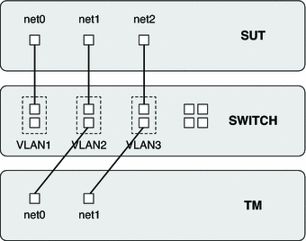
The Jumbo Frame test case is designed to verify the jumbo frame functionality supported by the switch. To do this, the switch, SUT and TM must be configured with support to jumbo frame.
The Jumbo Frame test case running environment can be schematically represented as shown in the following figure.
Figure 6-2 Jumbo Frame Test Case
 To Set Up Jumbo Frame Test Case
- Configure the switch by executing the following steps.
- Setup three VLANs: VLAN1, VLAN2 and VLAN3 on the switch, and ensure
that each VLAN includes two switch ports.
- Assign an IP address to VLAN1. Select one switch port of VLAN1 as
administrator port and connect it to SUT.
- Set the Maximum Transmission Unit (MTU) size of the switch ports supported for
each port in VLAN2 and VLAN3.
- Configure the Test Manager by executing the following steps.
- Setup the TM in manual mode. Select two links NET0 and NET1
as test links, and assign the IP address to each link by
the TM.
- Connect NET0 to the port of VLAN2, and NET1 to the port of
VLAN3.
- Configure the System Under Test by executing the following steps.
- Setup the SUT in manual mode. Select three links NET0, NET1 and
NET2 as test links, and assign the IP address to the each link
by the SUT.
- Save the test type, NET1 and NET2 IP address of SUT, NET0 and
NET1 IP address of TM and switch ports MTU size into /opt/SUNWhcts/etc/switch.conf file respectively.
- Connect NET0 to the port of VLAN1, NET1 to the port of
VLAN2, NET2 to the port of VLAN3.
- Setup three VLANs: VLAN1, VLAN2 and VLAN3 on the switch, and ensure that each VLAN includes two switch ports.
- Assign an IP address to VLAN1. Select one switch port of VLAN1 as administrator port and connect it to SUT.
- Set the Maximum Transmission Unit (MTU) size of the switch ports supported for each port in VLAN2 and VLAN3.
- Setup the TM in manual mode. Select two links NET0 and NET1 as test links, and assign the IP address to each link by the TM.
- Connect NET0 to the port of VLAN2, and NET1 to the port of VLAN3.
- Setup the SUT in manual mode. Select three links NET0, NET1 and NET2 as test links, and assign the IP address to the each link by the SUT.
- Save the test type, NET1 and NET2 IP address of SUT, NET0 and NET1 IP address of TM and switch ports MTU size into /opt/SUNWhcts/etc/switch.conf file respectively.
- Connect NET0 to the port of VLAN1, NET1 to the port of VLAN2, NET2 to the port of VLAN3.
Example 6-2
The following example displays how to set up a Jumbo Frame test case.
For a switch, there are three VLANS: VLAN1, VLAN2 and VLAN3:
      . show vlan
      VLAN Name                         Status    Ports
      ---- -------------------------------- --------- ---------------
      ... ...
      5    VLAN1                        active    Gi1/1, Gi1/2
      30   VLAN2                        active    Gi1/11, Gi1/12
      40   VLAN3                        active    Gi1/21, Gi1/22
      The switch administration port IP address for VLAN1:

      .show int vlan 5
      Vlan5 is up, line protocol is up
        Hardware is Ethernet SVI, address is c471.fe8b.9bff (bia c471.fe8b.9bff)
        Internet address is 192.168.1.10/24
        MTU 9198 bytes, BW 1000000 Kbit, DLY 10 usec,
        ? ?
       The switch ports MTU size in VLAN2 and VLAN3:

       .show int Gi1/11
       GigabitEthernet1/11 is up, line protocol is up (connected)
         ... ...
         MTU 9198 bytes, BW 1000000 Kbit, DLY 10 usec,
         ... ...
For SUT, there are three links net0, net1, net2 which has to be configured as test links.
root@solairs:~# ifconfig -a
        net0: flags=100001000843<UP,BROADCAST,RUNNING,MULTICAST,IPv4,PHYSRUNNING>
mtu 1500 index 5
                inet 192.168.1.10 netmask ffffff00 broadcast 192.168.1.255
                ether 0:10:e0:46:5c:f9
        net1: flags=100001000843<UP,BROADCAST,RUNNING,MULTICAST,IPv4,PHYSRUNNING>
mtu 9000 index 8
                inet 192.168.10.10 netmask ffffff00 broadcast 192.168.10.255
                ether 0:10:e0:46:5c:fa
        net2: flags=100001000843<UP,BROADCAST,RUNNING,MULTICAST,IPv4,PHYSRUNNING>
mtu 9000 index 9
                inet 192.168.11.10 netmask ffffff00 broadcast 192.168.11.255
                ether 0:10:e0:46:5c:fb
        The ethernet network switch certification test configuration file on SUT:
        root@solairs:~# cat /opt/SUNWhcts/etc/switch.conf
       ... ...
        # Jumbo Frame testing
        # Argument 1: SUT NIC IP Address
        # Argument 2: TM NIC IP Address
        # Argument 3: Switch port MAX MTU size
        # Example: JF 10.10.50.10 10.10.50.11 9000
        JF 192.168.10.10 192.168.10.11 9198
        JF 192.168.11.10 192.168.11.11 9198
       ... ...
For TM, there are two links net0 and net1 which has to be configured as test links.
root@solairs:~# ifconfig -a
       net0: flags=100001000843<UP,BROADCAST,RUNNING,MULTICAST,IPv4,PHYSRUNNING>
mtu 9000 index 112
               inet 192.168.10.11 netmask ffffff00 broadcast 192.168.10.255
               ether 0:10:e0:10:15:c7
       net1: flags=100001000843<UP,BROADCAST,RUNNING,MULTICAST,IPv4,PHYSRUNNING>
mtu 9000 index 113
               inet 192.168.11.11 netmask ffffff00 broadcast 192.168.11.255
               ether 0:10:e0:10:15:c8
Port Mirroring Test Case
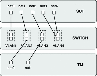
The Port Mirroring test is designed to test the data transmit/receive functionality in port mirroring mode.
The Port Mirroring test case running environment can be schematically represented as shown in the following figure.
Figure 6-3 Port Mirroring Test Case
 To Set Up Port Mirroring Test Case
- Configure the switch by executing the following steps.
- Setup four VLANs: VLAN1, VLAN2, VLAN3 and VLAN4 on the switch, and
ensure that each VLAN includes two switch ports.
- Assign an IP address to VLAN1. Select one switch port of VLAN1 as
administrator port and connect it to SUT.
- Set the port which connects to NET3 of SUT in VLAN4 to mirror
the port which connects to NET1 of SUT. Set the port which connects
to NET4 of SUT in VLAN4 to mirror the port which connects
to NET2 of SUT.
- Configure the Test Manager by executing the following steps.
- Setup the TM in manual mode. Select two links NET0 and NET1
as test links, and assign the IP address to each link by
the TM.
- Connect NET0 to the port of VLAN2, and NET1 to the port of
VLAN3.
- Configure the System Under Test by executing the following steps.
- Setup the SUT in manual mode. Select five links NET0, NET1, NET2,
NET3 and NET4 as test links, and assign the IP address to
NET0, NET1 and NET2 by the SUT in manual mode.
- Save the test type, NET3 and NET4 link name of SUT, NET0 and
NET1 IP address of TM into /opt/SUNWhcts/etc/switch.conf file respectively.
- Connect NET0 to the port of VLAN1, NET1 to the port of
VLAN2, NET2 to the port of VLAN3, NET3 and NET4 to the ports of
VLAN4.
- Setup four VLANs: VLAN1, VLAN2, VLAN3 and VLAN4 on the switch, and ensure that each VLAN includes two switch ports.
- Assign an IP address to VLAN1. Select one switch port of VLAN1 as administrator port and connect it to SUT.
- Set the port which connects to NET3 of SUT in VLAN4 to mirror the port which connects to NET1 of SUT. Set the port which connects to NET4 of SUT in VLAN4 to mirror the port which connects to NET2 of SUT.
- Setup the TM in manual mode. Select two links NET0 and NET1 as test links, and assign the IP address to each link by the TM.
- Connect NET0 to the port of VLAN2, and NET1 to the port of VLAN3.
- Setup the SUT in manual mode. Select five links NET0, NET1, NET2, NET3 and NET4 as test links, and assign the IP address to NET0, NET1 and NET2 by the SUT in manual mode.
- Save the test type, NET3 and NET4 link name of SUT, NET0 and NET1 IP address of TM into /opt/SUNWhcts/etc/switch.conf file respectively.
- Connect NET0 to the port of VLAN1, NET1 to the port of VLAN2, NET2 to the port of VLAN3, NET3 and NET4 to the ports of VLAN4.
Example 6-3
The following example displays how to set up a Port Mirroring test case.
For a switch, there are four VLANS: VLAN1, VLAN2, VLAN3, and VLAN4:
     . show vlan
      VLAN Name                        Status    Ports
      ---- -------------------------------- --------- --------------------
      ... ...
      5    VLAN1                        active    Gi1/1, Gi1/2
      30   VLAN2                        active    Gi1/11, Gi1/12
      40   VLAN3                        active    Gi1/21, Gi1/22
      50   VLAN4                        active    Gi1/31, Gi1/32
      The switch administration port IP address for VLAN1:

      .show int vlan 5
      Vlan5 is up, line protocol is up
        Hardware is Ethernet SVI, address is c471.fe8b.9bff (bia c471.fe8b.9bff)
        Internet address is 192.168.1.10/24
        MTU 9198 bytes, BW 1000000 Kbit, DLY 10 usec,
        ... ...
        The mirroring configuration:

        .show monitor
        Session 1
        ---------
        Type                   : Local Session
        Source Ports           :
            Both               : Gi1/11
        Destination Ports      : Gi1/31
            Encapsulation      : Native
                  Ingress      : Disabled
                 Learning : Disabled
        Filter Pkt Type        :
            RX Only       : Good
        ... ...
For SUT, there are four links net0, net1, net2, and net3 which has to be configured as test links.
root@solairs:~# ifconfig -a
        net0: flags=100001000843<UP,BROADCAST,RUNNING,MULTICAST,IPv4,PHYSRUNNING>
mtu 1500 index 5
                inet 192.168.1.10 netmask ffffff00 broadcast 192.168.1.255
                ether 0:10:e0:46:5c:f9
        net1: flags=100001000843<UP,BROADCAST,RUNNING,MULTICAST,IPv4,PHYSRUNNING>
 mtu 1500 index 8
                inet 192.168.10.10 netmask ffffff00 broadcast 192.168.10.255
                ether 0:10:e0:46:5c:fa
        net2: flags=100001000843<UP,BROADCAST,RUNNING,MULTICAST,IPv4,PHYSRUNNING>
mtu 1500 index 9
                inet 192.168.11.10 netmask ffffff00 broadcast 192.168.11.255
                ether 0:10:e0:46:5c:fb
        net3: flags=100001000843<UP,BROADCAST,RUNNING,MULTICAST,IPv4,PHYSRUNNING>
mtu 1500 index 10
                inet 0.0.0.0 netmask ff000000
                ether 90:e2:ba:71:67:c
        net4: flags=100001000843<UP,BROADCAST,RUNNING,MULTICAST,IPv4,PHYSRUNNING>
mtu 1500 index 11
                inet 0.0.0.0 netmask ff000000
                ether 90:e2:ba:71:67:d

        The ethernet network switch certification test configuration file on SUT:
        root@solairs:~# cat /opt/SUNWhcts/etc/switch.conf
       ... ...
        # Port mirroring testing
        # Argument 1: SUT nic interface linked to mirrored port outside test vlan
        # Argument 2: TM nic ip address linked to port in test vlan
        # Example: PM net0 10.10.10.10
        PM net3 192.168.10.11
        PM net4 192.168.11.11
       ... ...
For TM, there are two links net0 and net1 which has to be configured as test links.
root@solairs:~# ifconfig -a
       net0: flags=100001000843<UP,BROADCAST,RUNNING,MULTICAST,IPv4,PHYSRUNNING>
mtu 1500 index 112
               inet 192.168.10.11 netmask ffffff00 broadcast 192.168.10.255
               ether 0:10:e0:10:15:c7
       net1: flags=100001000843<UP,BROADCAST,RUNNING,MULTICAST,IPv4,PHYSRUNNING>
mtu 1500 index 113
               inet 192.168.11.11 netmask ffffff00 broadcast 192.168.11.255
               ether 0:10:e0:10:15:c8
Link Aggregation Test Case
The Link Aggregation test case is designed to test the data transmit/receive functionality in Link Aggregation mode.
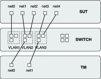
The Link Aggregation test case running environment can be schematically represented as shown in the following figure.
Figure 6-4 Link Aggregation Test Case
 To Set Up a Link Aggregation Test Case
Before You Begin
Ensure that the versions of System Under Test and Test Manager is higher than Oracle Solaris 11.1.
While Link Aggregation test case is running, the user needs to unplug one data link cable of the link aggregation from the switch port manually at a random time.
Besides setting up the SUT and TM in manual mode for network certification, the user also needs to write the /opt/SUNWhcts/etc/switch.conf file before starting the test case.
- Configure the switch by executing the following steps.
- Setup three VLANs: VLAN1, VLAN2 and VLAN3 on the switch, and ensure that each VLAN includes three switch ports.
- Assign an IP address to VLAN1. Select one switch port of VLAN1 as administrator port and connect it to SUT.
- Set the two ports which connect to NET1 and NET2 of SUT into one port-channel in VLAN2, and set the two ports which connect to NET3 and NET4 of SUT into one port-channel in VLAN3.
- Configure the Test Manager by executing the following steps.
- Setup the TM in manual mode. Select two links NET0 and NET1 as test links, and assign the IP address to each link by the TM.
- Connect NET0 to the port of VLAN2, and NET1 to the port of VLAN3.
- Configure the System Under Test by executing the following steps.
- Setup the SUT in manual mode. Select five links NET0, NET1, NET2, NET3 and NET4 as test links, bind NET1 and NET2 as LAG0, bind NET3 and NET4 as LAG1, and assign IP address to LAG0 and LAG1. For more information about link aggregation in Oracle Solaris, please refer to the Overview of Link Aggregations section in the Oracle Solaris Administration: Network Interfaces and Network Virtualization guide.
- Save the test type, NET0 and NET1 IP address of TM into /opt/SUNWhcts/etc/switch.conf file respectively.
- Connect NET0 to the port of VLAN1, NET1 and NET2 to the ports of VLAN2, NET3 and NET4 to the ports of VLAN3.
Example 6-4
The following example displays how to set up Link Aggregation test case.
For a switch, there are three VLANS: VLAN1, VLAN2 and VLAN3:
     . show vlan
      VLAN Name                         Status    Ports
      ---- -------------------------------- --------- ---------------------
      ... ...
      5    VLAN1                        active    Gi1/1, Gi1/2
      30   VLAN2                        active    Gi1/11, Gi1/12
      40   VLAN3                        active    Gi1/21, Gi1/22
      The switch administration port IP address for VLAN1:

      .show int vlan 5
      Vlan5 is up, line protocol is up
        Hardware is Ethernet SVI, address is c471.fe8b.9bff (bia c471.fe8b.9bff)
        Internet address is 192.168.1.10/24
        MTU 9198 bytes, BW 1000000 Kbit, DLY 10 usec,
        ... ...
       The link aggregation configuration:

       .show etherchannel summary
       ... ...
       Group  Port-channel  Protocol    Ports
       ------+-------------+-----------+-----------------------------------
       1      Po1(SD)         LACP      Gi1/11(D)   Gi1/12(D)
       ... ...
For SUT, there are three links net0, lag0, and lag1 which has to be configured as test links.
                 root@solairs:~# ifconfig -a
        net0: flags=100001000843<UP,BROADCAST,RUNNING,MULTICAST,IPv4,PHYSRUNNING>
mtu 1500 index 5
                inet 192.168.1.10 netmask ffffff00 broadcast 192.168.1.255
                ether 0:10:e0:46:5c:f9
        lag0: flags=1000803<UP,BROADCAST,MULTICAST,IPv4> mtu 1500 index 12
                inet 192.168.10.10 netmask ffffff00 broadcast 192.168.10.255
                ether 0:10:e0:46:5c:f9
        lag1: flags=1000803<UP,BROADCAST,MULTICAST,IPv4> mtu 1500 index 13
                inet 192.168.11.10 netmask ffffff00 broadcast 192.168.11.255
                ether 0:10:e0:46:5c:fb
        The ethernet network switch certification test configuration file on SUT:
        root@solairs:~# cat /opt/SUNWhcts/etc/switch.conf
       ... ...
        # Link aggregation testing
        # Argument 1: TM nic ip address
        # Example: LAG 10.10.30.11
        LAG 192.168.10.11
        LAG 192.168.11.11
       ... ...
For TM, there are two links net0 and net1 which has to be configured as test links.
       root@solairs:~# ifconfig -a
       net0: flags=100001000843<UP,BROADCAST,RUNNING,MULTICAST,IPv4,PHYSRUNNING>
mtu 1500 index 112
               inet 192.168.10.11 netmask ffffff00 broadcast 192.168.10.255
               ether 0:10:e0:10:15:c7
       net1: flags=100001000843<UP,BROADCAST,RUNNING,MULTICAST,IPv4,PHYSRUNNING>
mtu 1500 index 113
               inet 192.168.11.11 netmask ffffff00 broadcast 192.168.11.255
               ether 0:10:e0:10:15:c8
Certifying Ethernet Network Switch
To certify an Ethernet network switch, the user has to first set up the storage environment. The user can then certify the devices by using either the GUI or CLI. The following sections describe the procedures that need to be followed to certify an Ethernet network switch.
 To Certify Ethernet Network Switch on Test Server Using GUI
- Start the Oracle HCTS GUI on the test server.
- When prompted to select a mode for the machine, select System Under Test,
and then click the OK button.
- Click the Switch Certification button on the left panel of the main window.
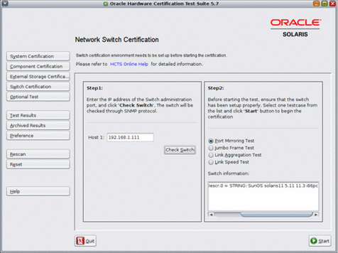
- Type the IP address of the switch administration port in the text field.
- Click the Check Switch button.
The Network Switch information found by Oracle HCTS is displayed on the right
text areas.
- Select any test case from the list.
- Click the Start button.
 To Certify Ethernet Network Switch on Test Server Using CLI
- To set up the test server as System Under Test (SUT), type
the following command.
# hctscli setup-sut
- To start the certification of an ethernet network switch on the test server,
type the following command.
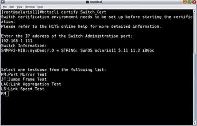
# hctscli certify Switch_Cert
The following message is displayed.
Switch certification environment needs to be set up before starting the
certification.
Please refer to HCTS Online Help for more detailed information.

Enter the IP address of the Switch Administration port:
- Type the IP address of the Switch Administration port.
- Type the test case name that you want to select.

The Network Switch information found by Oracle HCTS is displayed on the right text areas.
 To Certify Ethernet Network Switch on Test Server Using CLI
- To set up the test server as System Under Test (SUT), type
the following command.
# hctscli setup-sut
- To start the certification of an ethernet network switch on the test server,
type the following command.
# hctscli certify Switch_Cert
The following message is displayed.
Switch certification environment needs to be set up before starting the certification. Please refer to HCTS Online Help for more detailed information. Enter the IP address of the Switch Administration port:
- Type the IP address of the Switch Administration port.
- Type the test case name that you want to select.
Example 6-5
The following image shows an example of the steps for certifying the Ethernet Network switch.
